
A cold forging die rarely announces its failure in advance. One day the press runs smoothly at 45 strokes per minute, producing a two-step shaft with a flanged base. The next day the operator hears a dull click at the bottom of the stroke, and inspection reveals a punch broken cleanly at the junction between its head and its stem. The fracture face shows beach marks that trace back to a transition radius of 0.3 mm, specified because the customer's drawing permitted no larger feature. That small radius, combined with a punch load of 180 kN and a press misalignment of 0.05 mm between punch and die, turned a routine cold forging job into an unplanned tool rebuild and a full shift of downtime.
This is the reality of cold forging tool design. Unlike stamping dies, which mostly manage bending and shearing stresses, cold forging tools must survive contact pressures of 1,500 to 2,500 MPa for hundreds of thousands of strokes, while the workpiece strain-hardens during every stroke. The tool designer's job is not simply to copy the part geometry into a die cavity. It is to create a complete system of punch, die insert, stress ring, ejector, lubrication, and machine settings that keeps stresses within the fatigue limits of the tool material, holds the dimensional accuracy of the forged part, and delivers an economically viable tool life.
This article explains the practical principles of cold forging tool design for tool engineers, process planners, and production managers who work with cold forging presses. It covers the load environment, the function of each tool component, material selection, stress ring design, geometry rules, forming sequence planning, lubrication, failure prevention, and the influence of the press machine itself. The goal is to provide a set of design rules that can be applied directly to reduce tool breakage, minimise downtime, and improve the accuracy of cold forged components.
Cold forging deforms metal at room temperature, or slightly above it when heat generated by plastic deformation is retained in the tool and the workpiece. Because the metal never reaches its recrystallisation temperature, the workpiece strain-hardens continuously during the stroke. This means the force required to deform the part rises as the stroke progresses, and the final calibration phase of the stroke experiences the highest contact pressure.
From a tool designer's perspective, three numbers matter most. The first is contact pressure at the die shoulder and punch face. For structural carbon steels such as AISI 1018 or 1045, forward extrusion commonly generates contact pressures of 1,200 to 1,800 MPa, while backward extrusion of cup shapes can push punch-face pressure above 2,000 MPa. The second is the accumulated plastic strain imposed on the workpiece. A part with a 70 per cent reduction in cross-section accumulates enough strain to double the flow stress of the annealed starting material. The third is the number of strokes the tool must survive. A production campaign for a fastener, bearing ring, or shaft component typically runs from 50,000 to 500,000 parts, placing the tool material firmly in the high-cycle fatigue regime.
These conditions separate cold forging tool design from almost every other die discipline. A stamping die carries bending loads rarely above 500 MPa. A hot forging die operates at elevated temperature, but the workpiece flow stress is low, so die pressures stay below about 500 MPa. A cold forging tool must contain a workpiece that is simultaneously hard, strong, and abrasive, while transmitting forces that push the tool material close to its compressive yield strength. The table below compares the conditions that influence the tool design decision.
| Parameter | Hot forging | Cold forging |
|---|---|---|
| Workpiece temperature | 900–1,250 °C | 20–200 °C |
| Workpiece flow stress | 50–200 MPa | 500–1,500 MPa |
| Typical die contact pressure | 200–500 MPa | 1,000–2,500 MPa |
| Primary tool concern | Thermal fatigue and heat checking | Mechanical fatigue and wear |
| Tensile exposure of the die | Low | High, requires prestress |
| Achievable part tolerance | IT12–IT16 | IT7–IT9 |
The practical implication is that every design decision in a cold forging tool — the choice of tool steel, the number of stress rings, the polish of the cavity, the corner radii, the lubricant — exists to manage one or more of these extreme conditions. When a tool fails unexpectedly, it is almost always because the designer underestimated one of them.
A cold forging tool is an assembly of precision components acting together, not a single machined die block. A complete tool set normally includes:
Each component carries a distinct type of load. The punch works primarily in compression, but any misalignment or asymmetric part geometry adds bending. The die insert carries radial pressure from the workpiece that tries to expand it outward. The stress ring carries the resulting tensile hoop stress, which is safer for its material because the ring is selected for toughness and is not in contact with the workpiece. The ejector experiences compression during part removal, and the backing plates must resist local surface indentation at contact points.
The design process should follow a disciplined sequence. Start from the finished part drawing and define the forming stages in sequence before designing the individual die cavities. For each stage, design the cavity shape of the die insert and the punch profile. Estimate the maximum forming force and radial pressure. Select the tool material for each component. Design the stress ring assembly using the thick-wall cylinder rules explained later in this article. Finally, specify surface finish, coatings, lubrication, and the ejection system. Going directly from part geometry to machining without this analysis is the most common reason new cold forging tools fail in the tryout press.
The choice of tool material is the single decision that most directly determines the life of the tool and the cost per forged part. A cold forging tool must provide hardness at operating temperature, compressive strength above 2,000 MPa, sufficient toughness to resist cracking, and wear resistance against clean, abrasive metal surfaces. No single grade satisfies all requirements perfectly, so the designer balances them according to the operation.
Cold work tool steels such as AISI D2, A2, and O1 are the most economical choice for short runs and low-load applications. They offer good toughness and machinability, but their hardness and wear resistance are limited, and they soften quickly if frictional heat raises the tool above 200 °C. They remain useful for backing plates, holders, and short-run tooling.
High-speed steels such as M2 and M42 retain hardness at higher working temperatures and are the standard choice for extrusion punches and die inserts in medium-volume production. Their higher alloy content gives them better wear resistance than cold work tool steels. Powder-metallurgy high-speed steels, such as those close to PM-M4 composition, improve both wear resistance and toughness compared with conventional HSS, because their fine and uniformly distributed carbides reduce the number of crack initiation sites. They are now the default for long-run punches and high-load die inserts in cold forging.
Tungsten carbide, typically cobalt-bonded grades in the K05 to K20 range, offers the highest compressive strength and wear resistance of any common tool material. Carbide die inserts can survive millions of strokes in small-part extrusion and sizing operations. However, carbide has almost no ductility: it cracks easily under bending, impact, or misalignment. The tool assembly must therefore be designed to load the carbide only in compression, with rigid punch guidance and controlled impact velocity.
| Material family | Hardness | Compressive strength | Typical application |
|---|---|---|---|
| Cold work tool steel (D2, A2 class) | 58–62 HRC | 2,000–2,400 MPa | Short-run punches, dies, backers |
| High-speed steel (M2, M42 class) | 62–65 HRC | 2,500–3,200 MPa | Medium-run punches and die inserts |
| Powder-metal HSS (PM-M4 class) | 64–67 HRC | 3,000–3,800 MPa | Long-run punches, high-load dies |
| Tungsten carbide (K05–K20) | 88–92 HRA | 3,500–5,500 MPa | Die inserts for small extrusions and sizing |
A practical rule for initial selection: for parts with a maximum outer diameter below approximately 30 mm and production runs above 200,000 pieces, a carbide die insert with a PM-HSS punch is a reliable combination. For parts above 50 mm diameter, PM-HSS or HSS tools are more forgiving, because carbide dies of that size become heavy, expensive, and brittle. For very high radial loads, carbide inserts are used with two stress rings, as described in the next section.
Cold forging takes place at pressures that would burst an unreinforced hardened steel die on the very first stroke. The surrounding stress ring exists for one purpose: to place the die insert under a controlled compressive prestress so that the forging pressure must first cancel that prestress before the insert can experience tension.
The operating principle comes from thick-walled cylinder theory. When a hardened steel ring with an inside diameter slightly smaller than the outside diameter of the die insert is pressed or shrunk into position, the interference creates a radial pressure at the interface and a hoop stress distribution through both parts. The die insert receives compressive hoop stress on its outer surface, and the bore of the insert receives a smaller compressive stress. During forming, the radial pressure from the workpiece acts against the bore and partially cancels this precompression. If the interference is chosen correctly, the net hoop stress at the die bore remains compressive, or only slightly tensile, during the entire stroke. A compressive state prevents crack initiation and stops existing microcracks from propagating.
Interference values in cold forging tooling typically fall between 0.15 and 0.35 per cent of the mating diameter. For a die insert with a 50 mm outside diameter, an interference of 0.2 per cent equals 0.10 mm of diametral interference, which is a substantial amount when measured against the elastic limits of the materials. Heavy backward extrusion dies often use two or three concentric stress rings. Each ring has an interference fit with the next, distributing the radial pressure across a larger total cross-section so that the outer rings do not exceed their fatigue strength.
The stress ring itself is usually made of a tough, high-strength tool steel or maraging steel, heat-treated to about 45 to 55 HRC. Its bore must be ground and honed to the same precision as the outside diameter of the die insert, because any local high point concentrates stress at the interface. Sharp shoulders, oil holes, or keyways on the stress ring bore are frequent sites for fatigue cracks; generous radii and smooth transitions are mandatory.
A practical design sequence: first, determine the radial pressure expected at the die bore from the forming load and contact area. Second, select a die insert outside-to-inside diameter ratio of at least 2:1. Third, calculate the interference required to keep the bore in compression at maximum load. Fourth, check the equivalent stress in the die insert and the stress ring with a simple elastic calculation or finite element analysis. Fifth, if the stress ring is overstressed, add a second ring or change to a higher-strength material. This sequence is quick enough to apply at the concept stage and accurate enough to prevent the most common burst failures.
Most premature failures of cold forging tools can be traced to a small number of geometry decisions. Following a few concrete rules eliminates the majority of crack, galling, and chipping problems.
Specify generous transition radii. Every transition between a punch head and stem, a die shoulder and bore, or a backing plate edge acts as a stress raiser. A radius of 0.3 mm can concentrate stress by a factor of three compared with a radius of 3 mm. Use at least 1 mm radius on small tools and 2 to 3 mm on tools above 50 mm characteristic size. Where the part drawing demands a sharp corner, add a relief by moving the critical transition out of the main load path; for example, by stepping the part with a small undercut that will be machined after forging.
Use taper on the punch and relief zones in the die. Punch outside diameters should carry 1 to 3 degrees of taper along the working length. This reduces friction forces and prevents galling when the punch retracts. The die bore should contain a short bearing land of 2 to 5 mm at the exit of the forming zone, followed by a relief of 0.2 to 0.5 mm on diameter, so the part contacts the bore only in the bearing zone.
Provide enough wall thickness in the die insert. As a first approximation, the outside diameter of the die insert should be at least twice the largest bore diameter. For a 20 mm cavity, the die insert should have an outside diameter of at least 40 mm before the stress ring is added. Radial pressure at high reductions can crack a die whose wall is too thin, because the outer fibre goes into tension regardless of the stress ring.
Polish in the direction of material flow. The die cavity and punch working surfaces should be polished to Ra 0.2 micrometres or better, with the polishing marks aligned to the direction in which the metal slides. Polishing marks running across the flow direction create roughness that increases friction, traps the lubricant unevenly, and initiates galling.
Avoid undercuts and plan for extraction. If the part has a recess or a reverse taper that locks it in the die, the ejector must overcome the locking force on every stroke. Where possible, design the part with a small draft angle of 0.5 to 1 degree on external surfaces and a slight taper in internal cavities. If an undercut is unavoidable, consider a split die or a moving segment, but expect higher tool cost and ongoing maintenance.
Assign realistic tolerances. Cold forging typically holds IT7 to IT9, which is excellent for a forming process. Attempting to hold tighter tolerances pushes the tool closer to its elastic deflection limits and magnifies the effect of press misalignment and temperature changes. Tolerances on the tool components themselves should be five to ten times tighter than the part tolerance; a common starting ratio is part tolerance divided by five for the die cavity and punch dimensions.
Cold forging tool design cannot be completed from the final part drawing alone. Most cold forged components are produced in several forming operations, each with its own tool set. The sequence of operations determines the load on every tool and therefore defines the tool design for each stage.
A typical sequence for a flanged shaft might run as follows: shear wire or bar stock to length, soften or anneal if the incoming material is too hard, apply a conversion coating and lubricant, upset one end to form a preform head, forward extrude the shank to its final diameter, and calibrate the flange by a final sizing stroke. Each stage removes a controlled amount of deformation mass from the initial wire diameter.
The central design rule is to balance deformation per stage. Limiting the cross-section reduction to about 60 to 70 per cent per stage keeps die pressure and material strain within practical limits for most carbon and alloy steels. Above this range, the required punch force rises steeply, the tool pressure increases, and the workpiece can develop internal cracks or surface seams. For a deeply formed cup, three or four stages are routine: first backward extrusion of the cup, then redrawing of the cup wall, then ironing of the wall to final thickness, and finally trimming of the top edge.
Tool load is calculated from the flow stress of the workpiece and the projected contact area. As a first estimate, the required press force is the cross-section area of the workpiece at the forming zone multiplied by the flow stress at the relevant strain, times a friction factor of 1.2 to 1.5. This result must be compared against the press capacity and against the compressive strength of the punch. A long, slender punch can buckle before the press reaches its nominal tonnage: the slenderness ratio, which is length divided by diameter, should stay below five for unguided punches, and beyond that, guide sleeves or support bushings are required. For a medium-size extrusion, for example, a machine such as a BLKP400 balanced-stroke cold forging toggle press provides the required tonnage with a generous margin for the friction factor.
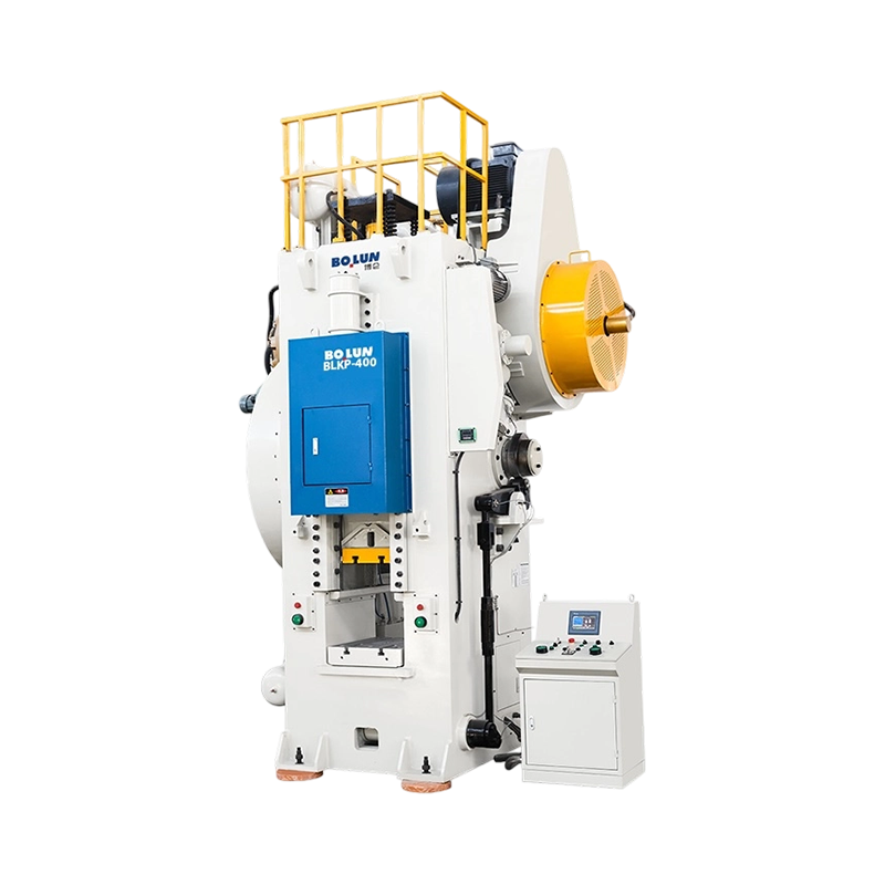 Wholesale BLKP-400 Versatile Balanced-Stroke Cold Forging Toggle Type Power PresZhejiang Bolun High-Precision Machinery Co., Ltd is China wholesale BLKP-400 Versatile Balanced-Stroke Cold Forging Toggle Type Power Pre...View Product →
Each stage affects the tool design of the next. A preform with a rough surface will scratch the next die. A preform that is slightly too large will overload the calibration die. A preform with an off-centre axis will create an uneven load and break the finishing punch. Tool designers should therefore specify preform dimensions with the same care as the final die cavity, including tolerances and surface finish. In practice, the forming sequence is designed first, the tools for each stage second, and a load check is repeated for every stage before any tools are manufactured.
Lubrication is not a detail added at the end of tool design; it is part of the tool system itself. In cold forging, the lubricant has three functions: reduce friction at the tool-workpiece interface, reduce the forming load transmitted to the tool, and prevent adhesive wear, often called galling, between the workpiece and the tool surfaces.
The standard lubrication system for carbon steels is a zinc phosphate conversion coating combined with a sodium stearate soap. The porous phosphate layer provides a mechanical anchor for the soap, and together they create a film with an apparent coefficient of friction in the range of 0.05 to 0.10. This system has been used for decades because it is effective and economical for high-volume production. Increasingly, environmental regulations are pushing manufacturers toward alternative lubricants, including polymer-based coatings and reactive soaps. When changing the lubricant system, the tool designer must recheck friction assumptions: higher friction increases punch and die wall pressures and may require larger tapers, shorter bearing zones, or additional stress ring interference.
Stainless steels, which work harden rapidly and gall easily, are usually lubricated with an oxalate conversion coating plus molybdenum disulfide. Aluminium and copper alloys use lower-viscosity oils or dry polymer films and do not require conversion coatings. For all materials, billets should be cleaned of scale, oil residues, and foreign particles before forming, because hard inclusions embedded in the lubricant film act as microscopic cutting tools on the die surface.
Tool coatings work together with the workpiece lubricant. PVD coatings such as chromium nitride, titanium aluminium nitride, and titanium nitride reduce friction, improve galling resistance, and protect the tool surface where the lubricant film locally breaks down. Coatings are especially useful on punches, which slide against the workpiece during retraction. The coating must be applied to a ground and polished substrate; a rough substrate gives poor adhesion and early flaking.
The important design quantity is the shear stress at the tool surface. If the frictional stress approaches the shear strength of the tool material or the coating, the surface tears and the tool fails quickly. Generous approach angles, short bearing lands, and a continuous lubricant film over the whole stroke are the most effective ways to keep surface shear stress within safe limits. A change in lubricant should always trigger a re-run of the load calculation, not just a line change in the production documentation.
Cold forging tools fail in patterns that are well understood within the industry. Recognising the pattern quickly tells the designer which parameter to change. The table below lists the most common failure modes, their main causes, and the design actions that prevent them.
| Failure mode | Main cause | Design countermeasure |
|---|---|---|
| Punch fatigue fracture | Cyclic compression and bending, stress concentration at a small transition radius | Increase transition radius; use PM-HSS; improve punch guidance; reduce impact speed near bottom dead centre |
| Die insert burst | Tensile hoop stress at the die bore | Increase stress ring interference; add a second stress ring; enlarge die outside diameter |
| Galling and scoring | Lubrication film breakdown, rough tool surface, local pressure peaks | Polish to Ra 0.2 or better; apply CrN or TiAlN coating; improve or change lubricant |
| Plastic deformation of punch face or die shoulder | Tool hardness lower than the required contact pressure | Select a harder HSS or carbide; enlarge the support area; reduce local contact pressure |
| Chipping at the die entrance | Impact from the billet end, hard scale, sharp entrance edge | Add an entrance chamfer or radius; coat the entrance; clean billets before forming |
| Stress ring fatigue crack | Excessive interference, stress concentration in the ring bore | Recalculate the shrink fit; enlarge ring outside diameter; remove keyways or sharp bore shoulders |
The most damaging failure mode is fatigue fracture of the punch. Punch loads are cyclic: the punch is compressed, unloaded, and compressed again tens or hundreds of thousands of times. If the stress amplitude at the smallest cross-section is high, a crack initiates at a transition radius or a grinding mark and propagates until fracture. The countermeasures are a larger transition radius, a tougher tool material, better alignment, and a controlled approach speed near bottom dead centre.
Die insert burst is the second most dangerous failure. The insert cracks radially through the wall, and the cavity opens elastically so the part becomes oversized before the insert is replaced. It is caused by insufficient prestress, which means the die bore went into tension under load. Increasing the interference or adding a second stress ring usually resolves it.
Galling appears as scoring on the punch surface and transferred particles on the workpiece. It is a lubrication and surface problem: the lubricant film broke down at a local high-pressure point. Polishing surfaces to a lower roughness, applying a low-friction coating, or increasing the lubricant supply usually stops it.
Plastic deformation of the punch face or die shoulder is a strength problem rather than a fatigue problem. The tool hardness is too low for the contact pressure, so the surface collapses by 0.02 to 0.1 mm and part dimensions drift out of tolerance. The solution is a harder tool grade, a carbide insert, or a design change that distributes the load over a larger area.
Cold forging tool design ends at the press-tool interface. The machine determines the load path, the speed, and the alignment that the tooling must tolerate, so the press deserves the same attention as the die itself.
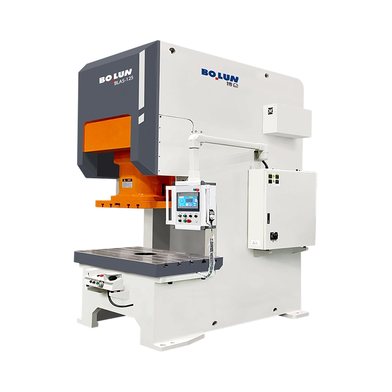
The first machine characteristic to consider is frame stiffness. An Open Type Power Press Machine, often called a C-frame press, deflects elastically under load, and the slide tilts relative to the bed. For a punch-die system, this angular misalignment adds bending moments to the punch and produces non-uniform loading in the die cavity. A closed-frame straight-side press, with its symmetrical column structure, deflects much less and maintains punch-die alignment under full rated load. Cold forging is a high-load, precision-sensitive process, so a rigid closed-frame press is the safer choice.
The second characteristic is the stroke curve. A conventional crank press reaches its maximum slide speed near mid-stroke and strikes the workpiece with high velocity. A toggle drive, also called a knuckle drive, slows the slide as it approaches bottom dead centre and develops high force with low impact velocity. This behaviour is nearly ideal for cold forging: the punch enters the billet gradually, the workpiece has time to flow, and the die is spared the impact shocks that initiate fatigue cracks. For this reason, toggle-type presses are the conventional machine concept for cold forging. Bolun's BLKP series is engineered around this principle; for example, the BLKP260 agile precision cold forging toggle press is suited to small precision parts such as pins, fasteners, and small shafts.
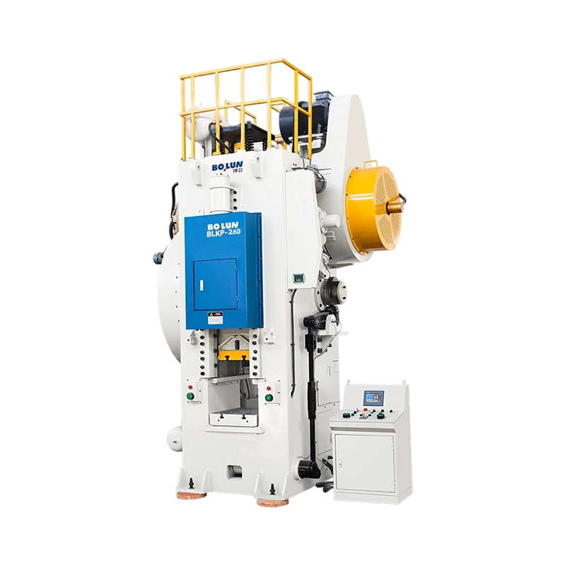 Wholesale BLKP-260 Agile Precision Cold Forging Toggle Type Power Press SupplierZhejiang Bolun High-Precision Machinery Co., Ltd is China wholesale BLKP-260 Agile Precision Cold Forging Toggle Type Power Press supplie...View Product →
The third characteristic is ram guidance. Precision guiding systems keep the punch concentric with the die at the moment of contact. Worn or loose guides introduce lateral displacement between punch and die, which raises the stress at the punch tip and can crack a carbide die insert even when the press tonnage appears sufficient. Regular checking of ram clearance and guide adjustment is inexpensive maintenance compared with a carbide die.
The machine also defines several tool parameters directly. Press tonnage must exceed the calculated forming force by at least 20 to 30 per cent. Shut height and stroke length determine the maximum tool stack height. Knockout force available in the bed and slide limits the design of ejectors for deep cavities. If the press has a hydraulic die cushion, its capacity determines whether a counteracting force can be applied during the stroke.
For heavy, high-deformation work such as large flanged shafts or long extrusions, the press must have both the tonnage and the energy to complete the stroke without stalling. The BLKP850 heavy-duty cold forging toggle press provides this industrial-scale capacity, while the balanced stroke curve protects the tooling from shock. Readers who want a broader comparison can refer to this introduction to cold forging press machines, and the full range of Bolun metal forming equipment is available on the company website.
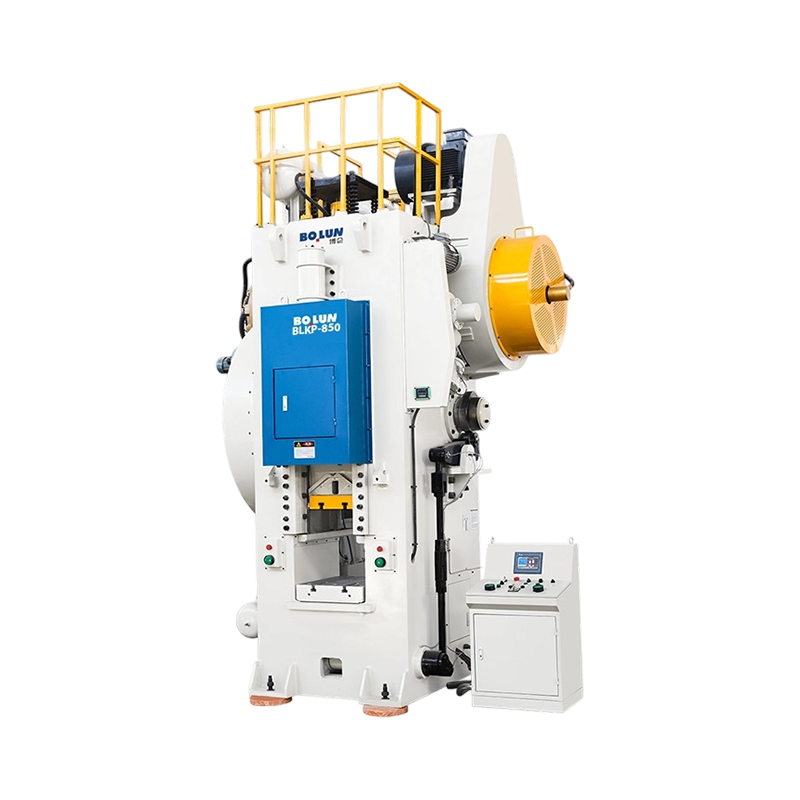 Wholesale BLKP-850 Industrial Strength Heavy-Duty Cold Forging Toggle Type PowerZhejiang Bolun High-Precision Machinery Co., Ltd is China wholesale BLKP-850 Industrial Strength Heavy-Duty Cold Forging Toggle Type Powe...View Product →
Even an experienced designer should validate a new cold forging tool before committing to machining. Finite element analysis is the most practical validation method for tool stress. A model of the die insert and stress ring assembly is loaded with the radial pressure from the workpiece at the die bore, and the shrink-fit interference between the rings is applied as the initial condition. The output is the stress distribution in every component. The designer checks that the die insert remains in its safe stress range and that the stress ring stays below its fatigue limit over the expected number of cycles.
Process simulation goes one step further by modelling the material flow of the workpiece inside the cavity. It reveals folding, underfilling, excessive strain concentration, and die load peaks before any steel is cut. The simulation also produces a realistic pressure distribution on the die surface, which is more accurate than assuming a uniform radial load. For high-volume production, the cost of the simulation is recovered quickly through fewer tryout iterations and longer tool life.
After manufacturing, a prototype tryout is still necessary. The tool is mounted on the press, trial parts are produced at reduced speed, and the actual forming load is measured with a load cell or by reading the press tonnage display. Dimensional inspection of the trial parts confirms the cavity geometry and any springback allowance. The first few hundred production parts deserve the same attention, because small variations in billet length, lubricant thickness, or tool temperature can change the forming load by several per cent.
Tool life records are a valuable but often neglected database. Recording the number of strokes to failure for each tool, the failure mode observed, and the maintenance history lets a shop build up practical experience. When a new tool design fails earlier than the previous one, the record shows which operation changed. Over time, this data turns tool design from a craft into a managed engineering process.
The following checklist summarises the design process described in this article. It is intended as a working reference when planning a new cold forging tool set.
A well-designed cold forging tool is the result of disciplined decisions about stress, geometry, materials, lubrication, and machine selection. When all of those decisions work together, the tool disappears into the background of production: it forms thousands of accurate parts, requires no unscheduled attention, and fails only after a predictable and economically sensible number of cycles. That quiet performance is the real measure of a good cold forging tool design.






A mid-size fastener manufacturer recently faced a familiar problem: its CNC lat...
A production manager at a mid-size metal component plant recently faced a probl...
When you are planning to produce medium or small metal parts in high volumes, t...
Understanding Mechanical Power Presses and Their Essential Functions A mechani...
A fastener plant in Taizhou receives a request from an automotive tier-one supp...
A production manager walks into an engineering meeting with a stack of drawings...
Contact Us

+86-575-83362228

+86-13735238388

+86-575-83362999

+86-15158259588

Hangzhou Office Add: No. 332 Wangjiang East Road, Shangcheng District

No.1 Linjiang Road East, Xiaren, Jinting Town, Shengzhou City, Zhejiang Province, China
Ready to Begin?
Get in Touch

Now!

ZHEJIANG BOLUN
 English
 中文简体
中文简体
