
Two presses can both carry a 200-tonne nameplate and still produce very different parts. A die shop that quotes a 2.5 mm mild-steel bracket on an open-gap press and then runs the same tool on a closed-frame press usually notices the change in edge camber, in burr height across the strip width, and in how often the die needs sharpening. The tonnage number did not change. What changed was how much the frame moved under load.
The practical conclusion comes first: when part tolerances are tight, the tool is a progressive die, or the bed is wider than roughly 1,200 mm, a closed type power press machine is normally the right starting point. The first things to negotiate are frame stiffness, usable die space and the drive characteristic, not the headline tonnage. For simple piercing and forming with generous tolerances and narrow coils, a well-built open-gap press often does the job for less money and gives better access from three sides.
Everything below explains where that dividing line actually sits, how to read a closed-frame specification sheet without being misled, and which details decide whether the machine runs cleanly for fifteen years or quietly becomes a source of scrap, downtime and die repairs.
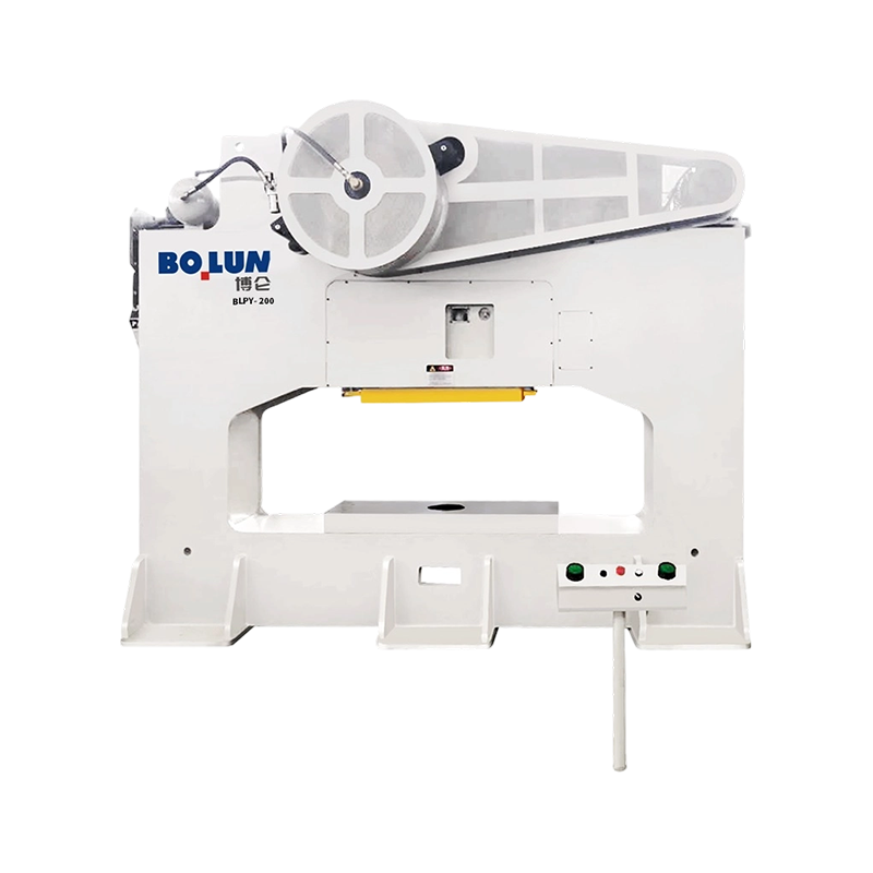
A press frame is a spring. Under load it stretches vertically and, in an open-gap design, it also rotates because the load path is C-shaped and only supported on one side. The vertical stretch is manageable; the angular rotation is what damages dies. When the slide tilts by a few hundredths of a millimetre across the bed, punch-to-die clearance stops being uniform. Cutting clearance in sheet metal is typically 5 to 8 percent of thickness per side, so on 1.5 mm stock the acceptable window is around 0.075 to 0.12 mm. A frame that rotates enough to eat half of that window at one end of the bed is effectively halving your die life and pushing burr height up on that side.
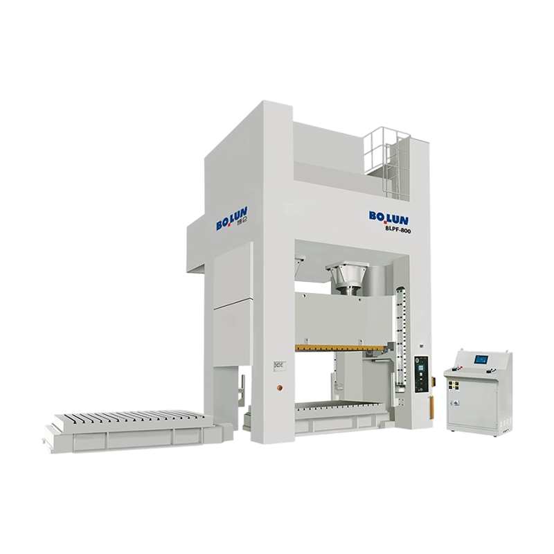
Closed-frame presses surround the load path with two uprights and a crown, so the force travels through a symmetric structure. Vertical deflection still exists, but angular deflection at the slide is far smaller, and slide-to-bolster parallelism stays within tolerance across the full bed width. In practice this is what buys you consistent burr height, better flatness on drawn parts, longer punch and die life, and the ability to run a progressive tool with four or six stations cutting at the same time without the strip walking sideways.
The trade-off is access. In a closed-frame machine the material normally enters front to back, coil lines and feeders are set in that direction, and side access for manual loading is limited. If your process depends on operators loading from three sides, or you need to hang long parts out of the side of the tool, an open-gap or semi-closed design is the more honest answer. Our own comparison of the two architectures, open-type versus closed-type power press explained, covers the geometry in more detail if you are still weighing the two.
| Selection factor | Open-gap press | Closed-frame press |
|---|---|---|
| Frame behaviour under load | Vertical stretch plus noticeable angular rotation of the gap | Predominantly vertical stretch, small angular error |
| Slide-to-bolster parallelism | Changes with load and load position | Holds closely across the bed width |
| Off-centre load tolerance | Low; load must stay near the gap centre | Moderate to high, especially with double-point slide |
| Part accuracy and burr consistency | Acceptable for general work | Better for tight tolerance and progressive work |
| Die life | Shorter where tilt is significant | Longer because clearance stays uniform |
| Operator and die access | Excellent from front, left and right | Front and back only; side access restricted |
| Typical tonnage band | Roughly 10 to 250 tonnes | Roughly 60 to 1,000 tonnes and above |
| Floor space for the same tonnage | Larger footprint relative to capacity | More compact per tonne of force |
Closed frames are not all built the same way, and the construction choice affects transport, maintenance and how the machine behaves after ten years of heavy blanking.
A monoblock frame is cast or fabricated as one piece, or welded and then stress-relieved and machined as a single unit. It is the stiffest option per kilogram of steel, has no pre-stress to relax, and gives the most predictable deflection curve. The constraint is logistics: the frame is the heaviest single item, it usually needs a flat-rack or break-bulk shipment rather than a container, and the rigging plan at your plant has to be settled before the purchase order, not after. Repair after a crash is also harder because there are no tie rods to re-shim.
Tie-rod frames are assembled from a crown, a bed and two or four uprights, clamped together by pre-stressed tie rods and nuts. The pre-stress is what makes the assembly stiff: the joint stays closed under working load because the rods were stretched at build time. This design ships in pieces, can be re-shimmed on site, and allows a frame repair without scrapping the whole structure. It also puts an obligation on the buyer: tie-rod pre-load must be checked periodically, nut tightness recorded, and the initial tension verified during installation. A tie-rod frame that has been assembled without correct pre-load will feel soft and will show it in die life.
A semi-closed machine keeps side columns but leaves the front and rear more open than a full closed frame. It sits between the two families and is useful where you want better stiffness than an open-gap press but still need generous front access for long or awkward parts. It is not a substitute for a true closed frame in a progressive die running near rated tonnage.
Whichever construction you choose, ask for the heaviest single piece, the lifting points and the centre of gravity. These three numbers decide your crane capacity, your door width and your installation cost, and they are frequently missing from a quotation that focuses only on tonnage and bed size.
The number of slide connection points is a load-path decision, not a marketing feature. A single-point slide is driven through one connecting rod at the centre of the slide. It is simple, cost-effective, and perfectly adequate when the working force stays near the middle of the bed and the tool is relatively narrow.
A double-point slide is driven through two connecting rods, one on each side. Under an off-centre load, the slide resists tilting far better, because the second connection point acts as a moment restraint. This matters in three common situations: progressive dies where several stations cut simultaneously at different positions, wide beds where the strip runs across 1,500 mm or more, and jobs where the tool is deliberately offset to one side to suit a coil line or a transfer system.
The practical rule is straightforward. If the die is wider than about 60 percent of the bed width, or if the tonnage is concentrated away from the centre by more than roughly a quarter of the bed length, a double-point machine is the safer choice. A single-point press can be run that way, but you are spending die life to save capital cost.
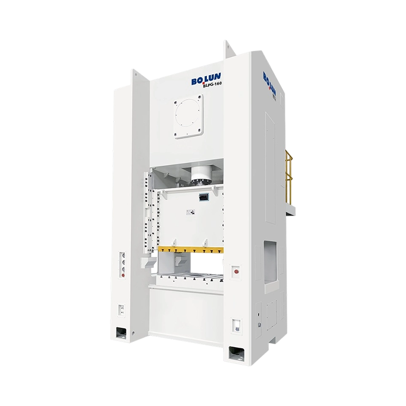
This is also where the wide-bed single-point machines earn their place. A closed single-point press with a wide door and a large bed, such as the BLPG series, gives good front access for large panels while keeping the closed-frame stiffness, and it suits jobs where the load is genuinely centred but the part is physically big. The double-point family, by contrast, is the workhorse for progressive and multi-station tooling. A representative example is the 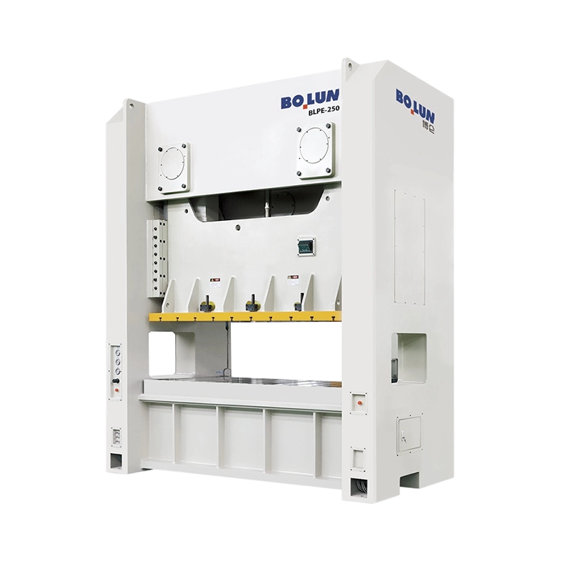 BLPE-250 Wide-Bed Closed-Frame Double-Point PressThe 2500 kN BLPE-250 pairs a 2500 × 1000 mm bed with closed-frame rigidity for large progressive and multi-station tooling.View Product → configuration, which pairs a wide bed with two connection points and a robust frame for continuous production work.
The frame decides how straight the machine stays. The drive decides what the slide does on the way down, and that in turn decides which processes the machine can actually perform. Four arrangements dominate closed-frame mechanical presses, and they are not interchangeable.
The classic crank drive converts rotary flywheel energy into a sinusoidal slide motion. It is efficient, mechanically simple and inexpensive to maintain. Slide velocity peaks at mid-stroke and falls towards bottom dead centre, so the material spends a reasonable time under compression near the bottom. Crank drives suit blanking, piercing, bending, shallow forming and general stamping where the force demand is close to the bottom of the stroke.
An eccentric gear drive places a large gear and an eccentric bearing between the flywheel and the connecting rod, which increases torque multiplication near bottom dead centre and allows a longer stroke without a proportionally larger crank throw. The result is high available force low in the stroke, which is exactly what deep drawing, cold forming and thick-plate work need. These machines tend to be the large ones: long stroke, wide bed, high tonnage, and a flywheel sized for a heavy single stroke rather than continuous light work. Where the job calls for deepstroke capability at high tonnage, the 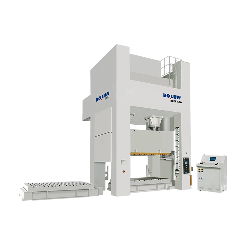 BLPF-630 Deep-Stroke Eccentric Gear Double-Point PressA 6300 kN eccentric-gear press with 400 mm stroke and 800 kN cushion for high-tonnage deep drawing and complex forming.View Product → specification is the kind of machine to compare against your forming energy calculation, not just your tonnage calculation.
A servo press replaces the flywheel and clutch with a motor and screw or crank mechanism that can be programmed. The slide can slow down through the cut, dwell at the bottom, reverse part-way, or approach fast and form slowly. That flexibility pays off in silent blanking, in drawing where you want a controlled punch speed through the material, in coining where a short dwell improves fill, and in jobs where the same machine must run several different tools. The limits are equally real: available torque at low speed, energy per stroke, motor and drive cost, and the fact that a servo machine's usable energy is finite in a way a large flywheel is not. If your process needs a very heavy single stroke, check the energy figure in kilojoules, not just the tonnage.
A frame-mounted double-point servo machine, such as the 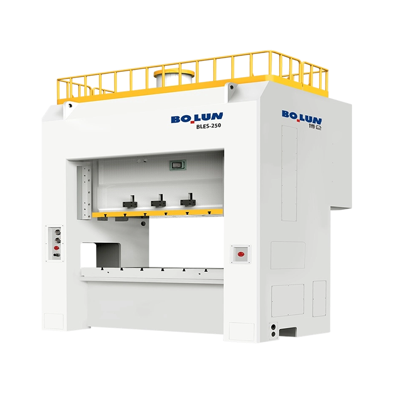 BLES-250 Closed-Frame Double-Point Servo PressA 2500 kN servo press with 25,200 J working energy and closed-frame double-point rigidity for programmable deep-drawing and precision stamping work.View Product → configuration, is the natural fit for a plant that runs mixed high-value work and wants programmable stroke profiles without giving up closed-frame rigidity.
Toggle drives multiply force dramatically near bottom dead centre through a linkage that straightens as the slide descends. The slide approaches slowly with high mechanical advantage, then retracts quickly. This is the standard architecture for cold forging, coining and sizing, where the material must flow rather than be cut, and where the force peak sits within a millimetre or two of the bottom. Toggle machines are usually specified by deformation energy and frame stiffness rather than by tonnage alone.
| Drive type | Force available near bottom dead centre | Typical processes | Main limitation to check |
|---|---|---|---|
| Crank | Rated force at the rated tonnage position | Blanking, piercing, bending, shallow forming | Stroke length and energy per stroke |
| Eccentric gear | High, with strong torque multiplication | Deep drawing, thick plate, cold forming | Flywheel recovery time on continuous strokes |
| Servo | Programmable; depends on motor and screw rating | Silent blanking, controlled drawing, coining, mixed tooling | Available energy per stroke and drive cost |
| Toggle / knuckle | Very high within a short working zone | Cold forging, sizing, coining | Narrow usable stroke window |
Most purchasing mistakes on closed-frame presses are not made on tonnage. They are made on the four or five numbers printed underneath it. A specification sheet is a contract in miniature, and each figure has a context that the quotation rarely explains.
Start with the rated tonnage position. A mechanical press can only deliver its nominal force at a defined distance above bottom dead centre, commonly somewhere between 5 and 13 mm depending on size and standard. Above that point, the drive geometry limits the force. If your forming operation needs full tonnage 30 mm above bottom dead centre, a machine rated at 6 mm will not deliver it, no matter what the nameplate says. Ask for the tonnage curve, not the single figure.
Next, check the stroke and the strokes per minute together. SPM is normally quoted at a specific stroke length and often at a specific speed setting. A machine advertised at 60 SPM may only reach that with a short stroke and a variable-speed drive set to maximum. If your tool needs a 200 mm stroke for part extraction, the realistic production rate may be considerably lower.
Then verify the die space arithmetic. Shut height, slide adjustment and bolster thickness must be read as a set. Your die stack should sit near the middle of the adjustment range, not at the extreme, so that you keep grinding allowance on the die and room to add a spacer or a cushion plate later. A die that only fits with the adjustment at its upper limit is a die that will not fit after its first regrind.
| Specification figure | What it controls | Question to ask |
|---|---|---|
| Rated tonnage and rated position | Usable force at a given height above bottom dead centre | Can you supply the tonnage curve across the working stroke? |
| Stroke length and SPM | Part extraction height and realistic output | At what stroke and speed setting is the SPM measured? |
| Die height and slide adjustment | Whether the die stack fits with margin | What is the adjustment position with my die installed? |
| Bed and slide area | Die footprint and clamping space | Is the quoted bed the frame opening or the bolster plate? |
| Frame deflection | Die clearance stability and part accuracy | What vertical and angular deflection is guaranteed at rated load? |
| Die cushion capacity and stroke | Blank holder force and ejection | Is cushion force constant through the stroke or rising? |
| Main motor power | Continuous output and energy recovery | How many strokes per minute can be sustained at full load? |
Tonnage should be calculated from the tool, then rounded up with a margin, then checked against the press curve. Doing it in the other order, starting from the machine you have been offered, is how presses end up running at 95 percent of rated load and failing early.
For shearing and blanking, the force is the cut length multiplied by thickness multiplied by the material's shear strength. A 180 mm square blank in 3 mm mild steel has a cut length of 720 mm; with a shear strength around 350 MPa, the force is roughly 756 kN, or about 77 tonnes. Add stripping force, typically 5 to 10 percent, and a working margin of 20 to 30 percent, and a 100 to 110 tonne machine is comfortable. Multiply by the number of stations cutting simultaneously in a progressive die. Four simultaneous cuts of that size will need well over 300 tonnes, which changes the machine class entirely.
For drawing, the draw force depends on the blank diameter, material thickness and tensile strength, and the blank holder force typically adds 20 to 40 percent on top. A common mistake is to size the press on draw force alone and forget that the cushion has to hold the blank down for the full draw depth while the slide is still moving. The cushion capacity, its force curve and its stroke all have to be checked against the drawing schedule, not just against the highest number in the catalogue.
Two further checks are often skipped. First, energy: a flywheel machine can deliver a large force but only a finite amount of energy per stroke before it slows down. A job with a long working stroke consumes more energy than a short blanking cut at the same tonnage, and if the flywheel cannot recover between strokes, production rate drops. Second, off-centre loading: closed frames tolerate it better than open-gap machines, but they do not ignore it. If the resultant force sits outside the recommended zone, the slide tilts, gibs wear unevenly, and the die sees clearance variation. Ask for the permissible off-centre load diagram and check where your tool's centre of force actually sits.
Die space is where good specifications go to die. A drawing that shows a 2,000 by 1,000 mm bed may be quoting the frame opening, while the actual bolster plate with T-slots may be smaller. Confirm which dimension you are buying, then confirm the T-slot size, pitch and position, because those decide how you clamp the die and whether your existing clamps and parallels will work.
Slide area matters as much as bed area. The upper die is clamped to the slide, and a slide that is much narrower than the die leaves the outer edges of the tool unsupported. For large panels this is a real source of flexing and marking. Also check the die weight limit against the slide and counterbalance capacity: an unbalanced heavy die will drop when the counterbalance pressure is released, which is both a safety issue and a die-damage issue.
On the cushion, the questions that matter are force, stroke and control. A pneumatic cushion gives a roughly constant force with a characteristic rise at the end of the stroke, which is fine for many drawing jobs. A hydraulic cushion with programmable force and position gives more control for difficult draws but adds cost and maintenance. If you intend to run both drawing and blanking work, check whether the cushion can be locked out or retracted clear of the die, and whether the cushion pins can be positioned to suit your tool layout without drilling new holes in the bolster.
For plants running high-mix, low-volume work, a moving bolster with rails and quick die clamping changes the economics more than any other option on the list. Setup time that drops from four hours to forty minutes pays back faster than a marginal reduction in cycle time, because the press can be earning money on the next job while the die is still being prepared.
A closed-frame press is a large investment protected by a small number of components, and the overload system is the most important of them. Hydraulic overload protection releases the slide when the force exceeds a set limit, usually within milliseconds, and then resets. Without it, a double blank or a misfed strip transfers the overload into the connecting rod, the crank and the frame. When comparing machines, ask what the overload release threshold is, how it is reset, and whether the release point can be verified during acceptance testing rather than taken on trust.
The clutch and brake arrangement determines stopping performance, noise and maintenance. Wet multi-plate clutches and brakes run in oil, last longer, run quieter and need less adjustment than dry friction types, at the cost of an oil circuit that must be maintained. What matters for safety is the stopping time and stopping angle, measured at the flywheel or slide, because the safety distance of the guarding and light curtains depends on it. Those figures should be recorded at commissioning and re-checked annually.
Lubrication is unglamorous and decisive. Automatic centralised lubrication with monitored pressure and a fault output prevents the most common cause of premature gib and gear wear. Ask for the lubrication diagram, the number of points, the reservoir capacity and the alarm behaviour when a line blocks. Also ask about warm-up procedure: a cold press has different clearances from a warm one, and a shop that starts at full tonnage on a cold morning will see accuracy drift for the first hour of the shift.
Press safety is regulated almost everywhere, and the requirement is not a sticker on the machine but a validated safety function. In markets following ISO 16092, mechanical presses are covered by a general safety standard for presses plus a machine-specific part for mechanical presses, and safety-related control systems are designed and validated to a performance level under ISO 13849. CE-marked machines in Europe, NR-12 in Brazil and OSHA-governed installations in the United States all approach the same problem from slightly different angles: the point of operation must be protected, and the protection must fail safely.
In practice, look for fixed guards with interlocked inspection doors, a two-hand control unit for single-stroke operation, light curtains or safety mats where access is needed, a safety block for die setting, and an energy isolation procedure that actually isolates stored energy in the flywheel, the counterbalance air and the hydraulic circuit. The safety block is often omitted from budget quotations and is essential for anyone who changes dies.
On the control side, the useful features are the ones that reduce operator error rather than the ones that look impressive in a brochure. Die height memory with motorised adjustment, tonnage monitoring with a per-stroke display, fault history with timestamps, and a clear indication of crank angle are all worth having. Tonnage monitoring in particular pays for itself the first time it catches a misfeed before the tool is destroyed.
A closed-frame press is stiff, heavy and sensitive to how it sits on the floor. The foundation is usually a separate reinforced concrete block, isolated from the surrounding slab, sized to the machine's mass and dynamic load and cast with anchor bolt pockets set from a template. Skipping the isolation and bolting straight to a general industrial slab is the fastest route to cracking, to vibration transmission into neighbouring machines, and to a press that will not hold parallelism.
Leveling is a precision job. A press leveled to a fraction of a millimetre per metre with a proper spirit or electronic level, then grouted and re-checked after the grout cures, will hold its geometry. One leveled by eye will show it in the first die. Allow curing time before production, and record the level readings as part of the installation file.
Utilities are usually underestimated. Compressed air is needed for the clutch, counterbalance, cushion and air blast; check pressure, flow and whether the supply is dry and filtered, because water in the air circuit reaches the clutch and the pneumatics. Electrical supply must match the motor and control voltage, and transformer capacity should be sized with starting current and any future servo or VFD load in mind. Leave room for a slug conveyor or a scrap bin under the bed, and confirm the pit depth required for the cushion and ejection.
Finally, plan the rigging. Confirm the crane capacity at the installation point, the door and passage widths, the floor loading along the route and whether the frame arrives assembled or in pieces. A machine that is ready on time but cannot be brought into the building is an expensive delay, and the rigging plan costs nothing to prepare in advance.
Before signing, walk through the following items and get each one answered in writing. None of them are exotic; all of them are routinely missed.
Total cost of ownership usually follows die life and uptime far more than purchase price. A machine that holds parallelism under load extends die life by a measurable margin, and a die that lasts 30 percent longer is worth more than a small discount on the press. Add the cost of scrap, of setup hours, of energy per thousand strokes and of unplanned downtime, and the cheapest quotation frequently stops being the cheapest option by year three.
Builders that manufacture both open and closed machines tend to structure their catalogue around the same four variables: frame architecture, number of slide connection points, drive type and process specialization. Understanding that structure makes it easier to shortlist the right model instead of reading thirty datasheets.
A typical closed-frame line runs from single-point wide-door machines for large, centred work, through double-point presses for progressive and multi-station tooling, into eccentric gear machines for deep drawing and heavy forming, and finally into servo-driven variants where programmable slide motion is worth the premium. Specialized branches sit alongside: cold forging toggle presses for deformation work, and battery shell presses for high-volume casing production where dimensional consistency across millions of parts matters more than raw tonnage.
Zhejiang Bolun High-Precision Machinery builds its closed-frame family along exactly these lines, with wide-door single-point models, double-point presses in the mid range, eccentric gear machines at the top of the tonnage scale, and a double-point servo branch for programmable forming. The company's stated position is as a vertically integrated manufacturer covering design, core component machining and final assembly, which matters to buyers mainly for one reason: the frame, the slide and the drive are produced under one roof, so the deflection and accuracy figures can be traced back to a machining and inspection process rather than assembled from third-party parts. Buyers evaluating the range can review the manufacturer's overview and then compare specific models against the specification checklist above.
The single most useful habit when buying a closed type power press machine is to stop treating tonnage as the headline specification. Tonnage tells you the size of the machine. Frame deflection, die space, drive characteristic and energy per stroke tell you what it will actually produce, how long the dies will last and whether the machine will still be holding tolerance in a decade. Get those four right, put the acceptance criteria in writing, and the rest of the purchase is administration.


A buyer comparing a 45-ton open-gap press for a bracket line often receives two...
A tooling engineer quotes a new bracket program and specifies a 160-ton press. ...
A mid-size fastener manufacturer recently faced a familiar problem: its CNC lat...
A production manager at a mid-size metal component plant recently faced a probl...
Understanding Mechanical Power Presses and Their Essential Functions A mechani...
Power press machines are classified in two main ways: by frame construction, w...
Contact Us

+86-575-83362228

+86-13735238388

+86-575-83362999

8618667502750

Hangzhou Office Add: No. 332 Wangjiang East Road, Shangcheng District

No.1 Linjiang Road East, Xiaren, Jinting Town, Shengzhou City, Zhejiang Province, China
Ready to Begin?
Get in Touch

Now!

ZHEJIANG BOLUN
 English
 中文简体

