
A tooling engineer quotes a new bracket program and specifies a 160-ton press. The die is built, the machine is installed, and on the first production run the slide stalls six millimetres above bottom dead centre. Nothing is broken. The tonnage was rated at the bottom of the stroke, and the work is being done higher up the curve, where the press can deliver only a fraction of that force.
That single mistake is why a press specification sheet is read in a particular order. Tonnage is the headline number, but stroke, speed, die height, bed size and the shape of the force curve decide whether a job runs at rate or fights the machine all day.
A power press converts the continuous rotation of an electric motor into a short, powerful, straight-line stroke. Energy is stored in a rotating flywheel, released through a clutch into a crankshaft, eccentric shaft or toggle linkage, and delivered to a slide that carries the upper die. The frame, the gibs, the die cushion and the counterbalance system all exist to keep that stroke accurate, repeatable and safe.
The sections below move from the mechanism to the numbers on the nameplate, then to the applications a power press actually serves, and finally to the decisions a buyer or process engineer has to make before signing a purchase order.
A power press is a machine tool that shapes metal by squeezing it between two matched tools. One tool is fixed to a stationary bed, the other to a moving slide. The press itself does not decide the shape of the part; the die does. The press decides how much force is available, how fast it can be applied, how accurately the slide can be guided, and how many times per minute the cycle can repeat without drift.
Four families of presses cover most metal forming work, and it is worth separating them before going further:
The interesting feature of the mechanical press is that its rated tonnage is not a constant. It is a maximum, valid at or near bottom dead centre. Move the work point up the stroke and the available force falls away. This is a design feature, not a defect: the flywheel stores kinetic energy and the crank converts it into a mechanical advantage that grows as the connecting rod approaches alignment with the slide. The trade-off is that the whole die design, the shut height and the process window all have to be planned around that curve.
| Assembly | Function | What buyers tend to check |
|---|---|---|
| Frame | Absorbs the reaction force of every stroke and holds the slide in alignment with the bed | Open C-frame or closed H-frame; cast or fabricated steel; measured deflection under load |
| Crown | Houses the drive shaft, flywheel, clutch and, on many designs, the slide adjustment motor | Access for service; rigidity under off-centre load |
| Crankshaft or eccentric shaft | Converts rotation into linear slide motion and sets the stroke length | Material and heat treatment; bearing type and lubrication circuit |
| Connecting rod and pitman | Transmits force from the shaft to the slide | Adjustment range; screw and locknut condition; backlash |
| Slide (ram) | Carries the upper die and travels on the gibs | Gib clearance, parallelism, slide face flatness, weight of tooling the slide will accept |
| Gibs and guideways | Keep the slide square to the bed throughout the stroke | Adjustable or fixed; lubrication; wear measurement interval |
| Bolster plate and bed | Supports the lower die and spreads the load into the frame | Bed area, T-slot pattern, thickness, cushion cut-out |
| Flywheel and clutch/brake | Stores energy between strokes and starts each stroke on demand | Clutch type (mechanical, air friction, wet, servo direct); brake stopping angle; single-stroke and inch modes |
| Counterbalance cylinders | Support the weight of the slide and tooling to reduce clearance and wear | Air pressure stability; reaction to tooling weight changes |
| Die cushion | Provides controlled resistance for drawing, stripping and ejection | Cushion capacity, stroke, whether it is pneumatic, hydraulic or servo controlled |
| Slide adjustment | Sets shut height to match the die set | Manual, motorised or hydraulic; resolution and repeatability |
| Control and safety system | Sequences the stroke and stops the machine when a guard is breached | Light curtains, two-hand control, muting, safe stop category, tonnage and die protection monitoring |
Two details in that table deserve more attention than they usually get. The first is deflection. A press frame does not simply absorb force; it bends slightly under it, and that bending opens the die clearance. A frame that deflects more than a few tenths of a millimetre across the bed will wear tooling faster and produce parts with tapered edges. The second is the die cushion, which is often treated as an accessory but is really the difference between a press that can draw and one that can only blank.
The sequence is easier to follow as a chain of energy conversions than as a list of parts. An electric motor spins a flywheel up to its running speed. The flywheel, not the motor, supplies the energy for the stroke. Between strokes, the motor restores the small amount of speed the flywheel lost during the previous cycle, which is why continuous heavy forming is limited by flywheel inertia and motor rating rather than by the die alone.
When the operator trips the press, the clutch engages and locks the flywheel to the crankshaft or eccentric shaft. The shaft turns, the connecting rod swings, and the slide travels down. Near the bottom of the stroke the crankshaft reaches the point where its leverage is greatest, and the die meets the material. The brake then stops the shaft, usually at top dead centre, and the clutch releases so the flywheel can recover speed while the operator unloads the part.
A servomotor-driven press replaces the flywheel, clutch and brake with a high-torque motor and a screw or crank mechanism. The slide motion is then programmable: the slide can slow down through contact, dwell at the bottom, reverse partway, or accelerate on the return stroke. This is the mechanism behind multi-mode forming, and it changes what is possible in deep drawing and in brittle or springy materials.
On a mechanical press, the useful force is concentrated in the last few millimetres before bottom dead centre. The practical consequence is that a job requiring maximum tonnage must be arranged so that the deformation happens close to the bottom of the stroke. Blanking and coining suit this perfectly, because the material shears or yields over a very short distance.
Drawing does not. A cup may need several centimetres of downward travel, and during that travel the press can only supply a fraction of its rated tonnage. This is why a press chosen for drawing tends to be significantly larger than a press chosen for blanking the same blank. Engineers who know this rule budget tonnage for the deepest point of the draw, not for the finished part weight.
There is a second, subtler consequence. Because the force curve is steep near the bottom, small variations in material thickness or hardness translate into large variations in the load the press sees. A coil that runs three hundredths of a millimetre thick on one pallet and thicker on the next will show up as tonnage spikes. Presses with tonnage monitoring and die protection watch exactly this, and they stop the machine before the spike becomes a cracked die or a stretched frame.
Four arrangements are common, and each changes the maintenance schedule as much as the performance envelope:
For a shop running two or three shifts, the difference between a dry friction clutch and a wet clutch is usually measured in downtime hours per year rather than in purchase price.
Press catalogues use a compact vocabulary. Every term on the sheet maps to a physical constraint in the tooling, and misreading one of them is the most common cause of a press that cannot run the job it was bought for.
| Term | What it means | Practical consequence |
|---|---|---|
| Rated tonnage | Maximum force available, normally stated near bottom dead centre | Must exceed the peak force of the operation, not the average force |
| Stroke length | Total travel of the slide from top to bottom dead centre | Must be long enough to load and unload the part, and to clear the die |
| Strokes per minute (SPM) | Cycle rate at rated speed | Sets theoretical output; handling and feeding usually become the real constraint |
| Die height / shut height | Distance from bed top to slide bottom at bottom dead centre, with adjustment at a stated position | Too little means the die set will not fit; too much can be corrected with spacers but costs rigidity |
| Slide adjustment | Range over which shut height can be changed | Determines how many different die sets the press can accept without risers |
| Bed and slide area | Usable mounting surface | Must contain the die footprint with room for clamps, not just the die outline |
| Throat depth | Distance from the frame to the centre of the slide on an open press | Limits the width of the sheet that can be fed through the side of an open-gap machine |
| Die cushion capacity and stroke | Force and travel available for drawing and stripping | A press without an adequate cushion cannot draw, regardless of tonnage |
| Window or opening dimensions | Clear space in the uprights of a closed-frame press | Determines whether coil feed, transfer arms or robots can reach the die area |
| Deflection under load | Frame stretch and slide tilt at rated tonnage | Drives die wear and part taper; matters most on wide beds and off-centre loads |
Two of these interact in a way that catches people out. Stroke length and die height trade off against each other: a longer stroke gives more room to feed and eject, but on many designs it also reduces the minimum shut height, because the crank throw and the slide position are geometrically linked. A press with a generous stroke may not accept a short die stack without a riser plate, and a riser plate adds a joint between the die and the bed that has to be shimmed and checked.
Off-centre loading is the other quiet problem. Catalogues quote tonnage for a centred load. A single-point press loaded to one side of the slide will tilt it, open the gib clearance on one side and close it on the other. The result is uneven part thickness, accelerated gib wear and, in the worst case, a cracked slide. When a die cannot be positioned centrally, the practical limit is commonly assumed to be around half the rated tonnage on a single-point machine and roughly two-thirds on a double-point machine, but the actual figure should come from the manufacturer's own load diagram rather than from a rule of thumb.
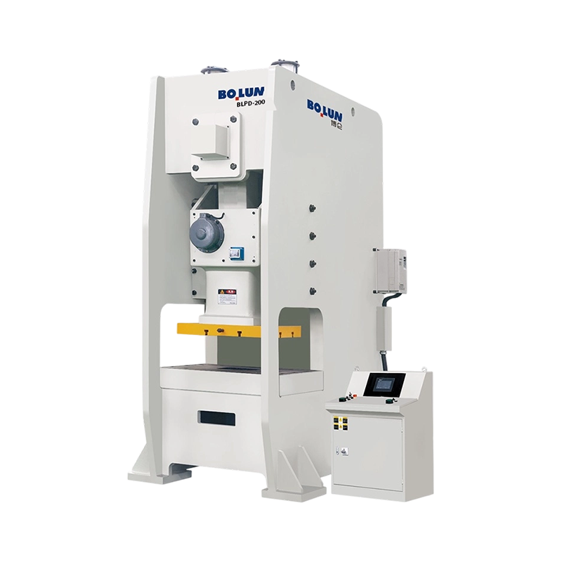
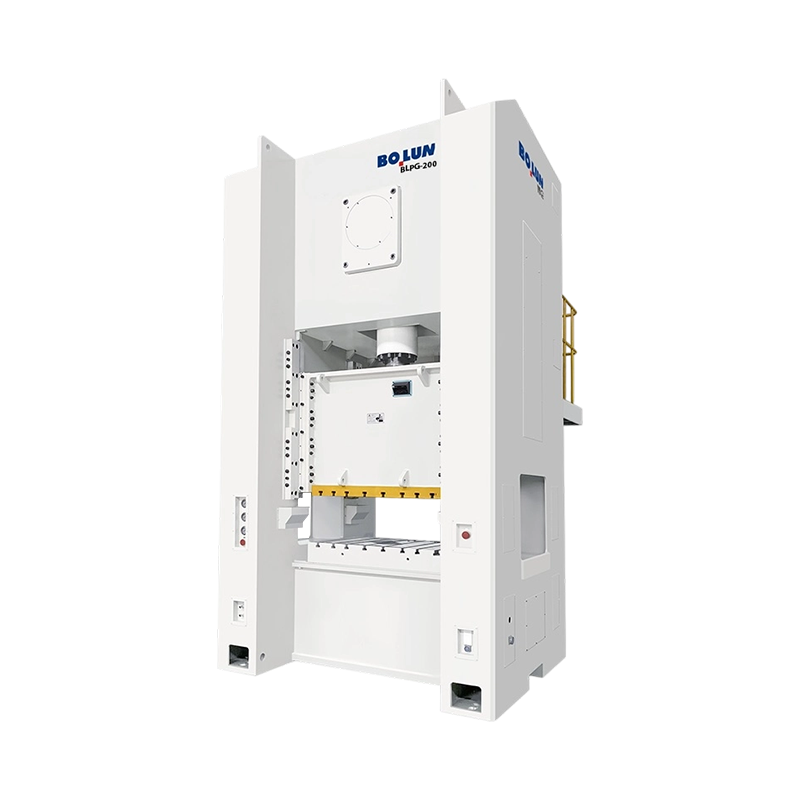
The frame is the first structural decision, and it is driven by part size, feeding method and tolerance. An open-type press has a C-shaped frame with the drive and slide supported from one side only. A closed-type press surrounds the slide on both sides, so the load path is symmetrical.
The consequence is straightforward. An open press gives three-sided access to the die, which makes manual loading, side feeding of long parts and quick die changes easy, but the frame is less stiff and deflects more under load. A closed press is far more rigid and is the normal choice for progressive dies, high tonnage, tight tolerances and any process where slide parallelism is critical. If the part is long and must be fed through the side, an open frame with a deep throat is often the only practical answer; if the part is a precision stamping produced at rate, the closed frame almost always wins on tool life. A more detailed treatment of the trade-offs is available in this comparison of open-type and closed-type press designs, which covers the deflection argument in more depth.
| Factor | Open-type (C-frame) | Closed-type (H-frame) |
|---|---|---|
| Load path | Asymmetric; frame acts as a cantilever | Symmetric; both uprights share the load |
| Deflection under load | Higher, and it tilts the slide | Low, with far less slide tilt |
| Access to the die | Three sides open | Front and rear windows only |
| Typical tonnage range | Light to medium | Medium to very heavy |
| Best suited to | Single-station dies, side-fed long parts, job shops and short runs | Progressive and transfer dies, high-volume stamping, tight tolerances |
| Die life | Shorter where tolerance is tight | Longer, because clearances stay stable |
| Footprint | Compact, easy to reposition | Larger, needs a substantial foundation |
| Automation fit | Simple with manual or robot loading from the side | Well suited to coil lines, transfers and in-press automation |
A hybrid deserves a mention because it is common in practice: the semi-closed or open-back frame. It adds a partial tie between the uprights behind the slide, which recovers a useful amount of rigidity while keeping most of the side access. It is a sensible middle ground for shops that need to run both single-station and moderate progressive work on the same machine.
Frame structure decides stiffness. The drive decides the shape of the stroke and, with it, the range of processes the press can run.
A crank drive is the simplest and cheapest arrangement. The crank radius sets the stroke, and slide velocity follows a sinusoidal curve that peaks in the middle of the downstroke. It is fast, efficient and ideal for blanking, piercing and shallow forming.
An eccentric gear drive places a gear between the flywheel and the eccentric shaft. The gear reduces speed and multiplies torque, so a heavier load can be moved with the same motor and clutch package. Eccentric gear presses are the traditional answer for deep-stroke, high-tonnage work such as large panel forming, where the slide has to travel a long way and still deliver force.
A toggle drive uses a linkage rather than a single crank. The mechanical advantage increases dramatically toward the bottom of the stroke, giving a slow approach, a short dwell and a very high force at the end of the travel. That combination is what makes toggle presses well suited to cold forging, coining and sizing operations, where the material must be forced to flow into a die cavity rather than simply sheared or bent.
A servo drive removes the fixed relationship between slide position and crank angle. The slide motion becomes a programmed profile. It can approach quickly, slow to a controlled speed at the moment of contact, dwell under load and return at high speed. In deep drawing this reduces the risk of tearing because the material is drawn at a rate it can tolerate; in forming of high-strength or springback-prone material it allows a calibration stroke at the bottom. The same flexibility supports multi-mode motion profiles that would be impossible on a fixed crank.
| Drive type | Stroke characteristic | Force at bottom of stroke | Typical applications |
|---|---|---|---|
| Crank | Fixed sinusoidal motion | Rated tonnage near BDC | Blanking, piercing, shallow forming, general stamping |
| Eccentric gear | Fixed, longer stroke with higher torque | High, sustained over a longer travel | Large panel forming, deep parts, heavy progressive dies |
| Toggle | Slow near the bottom with a short dwell | Very high, concentrated at the end | Cold forging, coining, sizing, thick-material forming |
| Servo | Programmable profile, dwell and reverse possible | Controlled and repeatable at any point in the profile | Deep drawing, springback-sensitive forming, multi-step operations |
The choice is not purely technical. A crank press costs less and is easier to maintain; a servo press costs more but can replace two conventional machines and a set of manual operations. The economics usually come down to how much of the saving in labour and secondary operations can be recovered over the life of the die.
Almost every mass-produced metal part has passed through a press at least once. The processes divide into a few recognisable groups, and each group makes specific demands on the machine.
Blanking cuts a shape out of sheet in one stroke; piercing punches holes in it. Both are shear operations completed over a very short distance, which means they suit the top of the force curve perfectly. The demands are high tonnage, a stiff frame to keep die clearance constant, and fast cycling. Progressive dies stack blanking, piercing, forming and trimming into one strip, and they need a closed-frame press with a rigid bed and good slide parallelism, because every station inherits the alignment error of the one before it.
These operations deform material rather than separating it. Bending and light forming need moderate force over a longer travel, so a press with a sensible stroke length and an adequately rated cushion is the right tool. Coining and embossing need the opposite: extreme force over almost no travel, which is where toggle and eccentric gear drives earn their place.
Deep drawing pulls a flat blank into a cup or shell, and the material must flow rather than stretch and tear. The force needed is moderate, but the slide must travel a long way and must do so at a speed the material can accept. This is the process where servo control makes the clearest difference, because the slide speed can be programmed independently at each stage of the draw. A servo press designed around this application, such as the 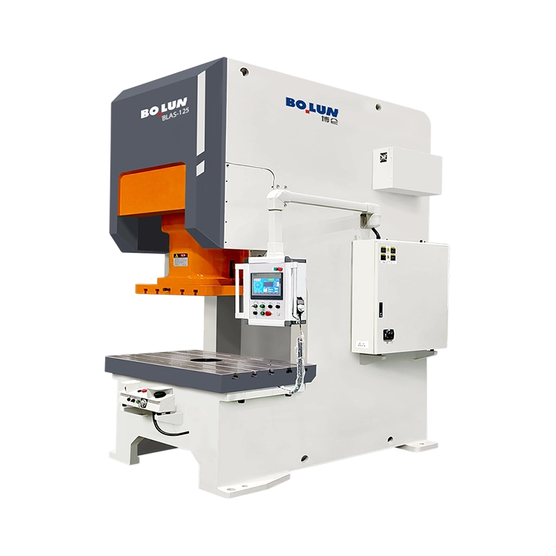 BLAS-125 Open-Type Single-Point Servo Press for Deep DrawingOpen-type single-point servo press for deep drawing and stretching, featuring high-torque direct drive, a 350 mm throat depth, and 1250 kN capacity.View Product → BLAS125 open-type single-point servo press, is specified for deep drawing and combines a long, controllable stroke with a cushion arrangement that suits cup work rather than simple blanking.
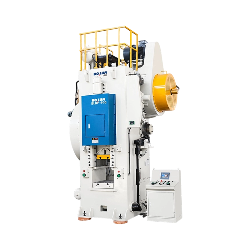
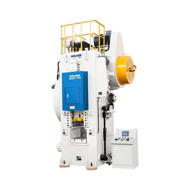
Cold forging forces metal to flow inside a die at room temperature. The forces are large, the deformation is severe, and the load arrives in a short, heavy pulse at the bottom of the stroke. Toggle-linkage presses are built for exactly this profile: a slow, powerful approach, a brief dwell that lets the material fill the cavity, and a quick return. Machines in this class, such as this 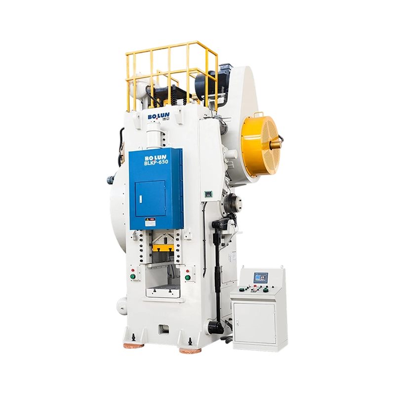 BLKP-650 High-Deformation Cold Forging Toggle Type PressHeavy-duty cold forging toggle press with 6500 kN capacity, 8 mm nominal pressure stroke, high-rigidity frame, and integrated ejector for severe deformation work.View Product → high-deformation cold forging toggle press, are designed around balanced stroke geometry, which keeps the slide square under the off-centre loads that forging dies generate, and around a frame that is stiff enough to hold the cavity dimensions through thousands of cycles.
Battery housings and similar enclosures are long, thin-walled drawn parts produced in very large quantities. The process is essentially a demanding draw with tight wall-thickness tolerance, shallow but repeated forming stages and a hard requirement that parts come out flat and square. Because the parts are often produced from wide coil on automated lines, the press needs a wide bed, a rigid closed or heavy open frame, and the ability to hold tolerance across the full bed width rather than just at the centre. Purpose-built machines such as this 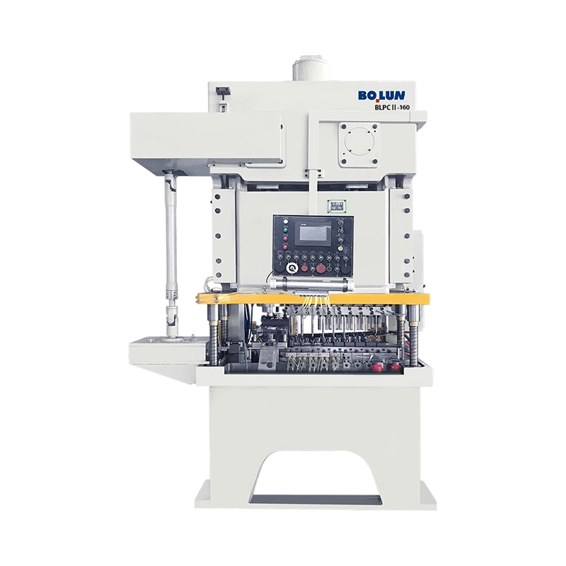 BLPC2-160 High-Tonnage Open-Type Double-Point Battery Shell PressOpen-type double-point battery shell press positioned for large-scale battery component forming and battery shell applications in high-volume production.View Product → high-tonnage, ultra-stable battery shell press are configured for that combination of bed width, tonnage and repeatability.
Not every job fits a compact die area. Wide panels, appliance wrappers and long structural sections need either a wide bed or a deep throat that lets the material pass beside the slide. Deep-throat open presses exist for exactly this reason: they trade some rigidity for the ability to feed a large sheet through the side of the machine while the die stays mounted on the bed.
Press selection goes wrong most often when the process is defined after the machine is purchased. Working in the reverse order takes longer at the quotation stage and saves months later.
The order matters because each step constrains the next. A change in the drawing depth, for example, can force a longer stroke, which changes the shut height envelope, which may force a different frame size entirely. Freezing the process first removes most of the back-and-forth.
The purchase price of a press is the smallest number in its lifetime cost. The larger numbers are tooling, energy, maintenance and unplanned downtime, and they are influenced by specification choices made years earlier.
Tooling life depends on alignment. Every tenth of a millimetre of slide tilt or frame deflection appears as uneven die clearance, and uneven clearance means burrs, edge wear, galling and cracked punches. A press that is stiff enough for the job will often pay for the difference in frame cost through extended die life alone, especially on progressive dies where a single station failure stops the whole line.
Energy consumption is dominated by the flywheel and motor sizing. A press with an oversized flywheel recovers speed more quickly between strokes and draws a steadier current, whereas one running at its limit cycles the motor hard and heats the enclosure. On servo presses the picture changes: the drive draws peak current during forming, so the electrical supply, cabling and any energy recovery arrangement deserve attention at the specification stage rather than at commissioning.
Safety requirements are non-negotiable and increasingly specific. Mechanical guarding, interlocked gates, light curtains with muting for automatic feed, two-hand control for manual load stations and a brake monitoring system that verifies stopping performance are the normal baseline. Tonnage monitoring and die protection are equally important in practice, because they turn a slow tooling failure into a stopped machine and a note in the maintenance log.
Two other costs are routinely underestimated. Compressed air is used for counterbalance, clutch actuation and pneumatic cushions, and leaks in that circuit show up as erratic clutch response and drifting slide balance. Lubrication is the second: automatic circulating systems with filtration and pressure monitoring convert what used to be a manual daily task into a scheduled filter change, and they catch a failing pump before it becomes a scored gib.
A mechanical press is a robust machine, but it wears in predictable places, and the wear is measurable long before it becomes visible in the parts.
A press that is maintained on a schedule can run for decades. A press run until something breaks usually takes a die, a production week and a customer relationship with it. The difference in cost between the two approaches is mostly administrative: a checklist, a set of tolerances and someone responsible for recording the numbers.
The final stage is verifying that the machine being offered will still be suitable in five years, when the part mix has changed and the tolerances have tightened. A few checks cover most of the risk.
Suppliers with in-house manufacturing tend to answer these questions with drawings and measurements rather than with adjectives. Bolun, for example, builds its press range around a full-chain production system that covers design, core component manufacture and final assembly, which is the arrangement that makes a load diagram and a deflection figure meaningful rather than approximate. Buyers evaluating a power press supplier should treat the ability to produce those numbers on request as a first filter, long before price enters the discussion.
A power press is a simple idea executed with unusual precision: store energy in a rotating mass, release it through a linkage that multiplies force, and guide the result so accurately that a die can cut, bend or draw metal to within a fraction of a millimetre, tens of thousands of times a day. Everything that matters in the specification follows from that sentence.
The tonnage tells you the ceiling. The force curve tells you where in the stroke you can use it. The frame tells you how much of it stays centred on the die. The drive tells you whether the motion is fixed or programmable. The cushion, the bed and the shut height tell you whether your tooling will fit and whether it will survive.
Get those five things right and the press becomes the least interesting machine in the plant, which is exactly what it should be. Get them wrong and it becomes the bottleneck every conversation starts with.



A fastener plant in Taizhou receives a request from an automotive tier-one supp...
Understanding Mechanical Power Presses and Their Essential Functions A mechani...
Power press machines are classified in two main ways: by frame construction, w...
What Is a Power Press? A power press — also called a stamping press or punch pr...
A production manager walks into an engineering meeting with a stack of drawings...
A cold forging die rarely announces its failure in advance. One day the press r...
Contact Us

+86-575-83362228

+86-13735238388

+86-575-83362999

+86-15158259588

Hangzhou Office Add: No. 332 Wangjiang East Road, Shangcheng District

No.1 Linjiang Road East, Xiaren, Jinting Town, Shengzhou City, Zhejiang Province, China
Ready to Begin?
Get in Touch

Now!

ZHEJIANG BOLUN
 English
 中文简体
中文简体
