
Power press machines are classified in two main ways: by frame construction, which separates them into Open Type Power Press Machines and Closed Type Power Press Machines, and by drive mechanism, which separates them into mechanical press machines, hydraulic presses, and pneumatic presses. Within the mechanical press category specifically, machines are further divided by how the ram is driven, including crank driven, eccentric driven, knuckle joint, toggle, and screw type designs, and by how many connection points support the ram, ranging from single point presses used for lighter work to four point presses used for large, heavy panels.
For most buyers, the practical decision comes down to two questions answered in sequence. First, does the application need the accessibility and lower cost of an Open Type Power Press Machine, or the rigidity and precision of a Closed Type Power Press Machine. Second, within whichever frame type fits the job, what tonnage, stroke length, and point configuration match the specific part being produced. The rest of this guide walks through every major classification of power press machine, compares open and closed frame designs directly with real operating data, explains drive mechanisms and point configurations in detail, and covers safety and maintenance practices that keep a press running reliably for years.
A power press machine is industrial equipment that applies controlled mechanical force through a moving ram to shape, cut, punch, or form sheet metal and other materials placed between the ram and a fixed bed. Unlike a manually operated press, a power press machine uses a motor driven system, most commonly a flywheel and crankshaft arrangement, to store and deliver the energy needed for each stroke, allowing much higher force output and far faster cycle times than manual operation could achieve.
In a typical mechanical power press, an electric motor continuously spins a flywheel, storing rotational energy. When the operator triggers a stroke, a clutch engages, connecting the spinning flywheel to a crankshaft or eccentric shaft. As that shaft rotates, it converts rotational motion into the linear up and down motion of the ram through a connecting rod, delivering a burst of stored energy to the workpiece at the bottom of the stroke, precisely when the tooling contacts the material.
The flywheel is central to how a mechanical power press achieves high force output from a relatively modest motor. Rather than requiring a motor powerful enough to deliver peak force instantaneously, the flywheel accumulates energy continuously between strokes and releases it in a short, powerful burst during the actual working portion of the stroke, allowing a comparatively small motor to drive a press capable of tonnage far exceeding what the motor alone could produce on a sustained basis.
A single press stroke moves through several distinct phases that operators and process engineers reference when troubleshooting or optimizing a stamping operation. The approach phase brings the ram down from top dead center toward the workpiece with minimal resistance. The working phase begins the moment tooling contacts material, consuming the bulk of the flywheel's stored energy as the actual cutting or forming takes place. The return phase then carries the ram back to top dead center, readying the press for the next cycle. Understanding where in this sequence a given operation places peak demand helps explain why certain drive mechanisms, such as knuckle joint or toggle designs, suit specific operations better than a standard crank drive, since each mechanism shapes this cycle differently to match a particular process need.
Power press machines are used across metal fabrication, automotive component manufacturing, appliance production, electrical enclosure manufacturing, and countless other industries requiring repeatable, high volume sheet metal operations such as blanking, piercing, bending, drawing, and coining, making this equipment category one of the most widely deployed classes of industrial machinery in modern manufacturing.
Before narrowing down to frame type, it helps to place the mechanical press machine within the broader landscape of press drive technologies, since each drive type suits a different production profile.
| Factor | Mechanical Press | Hydraulic Press | Pneumatic Press |
|---|---|---|---|
| Cycle speed | Fast, high strokes per minute | Slower, controlled ram speed | Very fast for light work |
| Force consistency through stroke | Varies through the stroke | Constant full force throughout stroke | Constant but limited force |
| Typical tonnage range | Moderate to very high | Wide range, including very high tonnage | Low to moderate |
| Best suited operations | Blanking, piercing, high volume stamping | Deep drawing, forming thick material | Light assembly, small part forming |
A mechanical press machine is generally the preferred choice whenever cycle speed and repeatable high volume output matter more than adjustable force control, which is why mechanical presses dominate high speed stamping lines in automotive and appliance manufacturing, while hydraulic presses remain preferred for deep drawing and thick material forming where controlled, constant force through the full stroke produces better results.
Pneumatic presses occupy a smaller but distinct niche, generally reserved for light duty applications such as small part assembly, light stamping, or press fit operations where the forces involved remain modest and extremely high cycle speed matters more than raw tonnage capability. Facilities rarely choose between all three drive types for a single application, since the required tonnage and operation type typically narrow the practical choice to one clear category before frame construction even enters the decision.
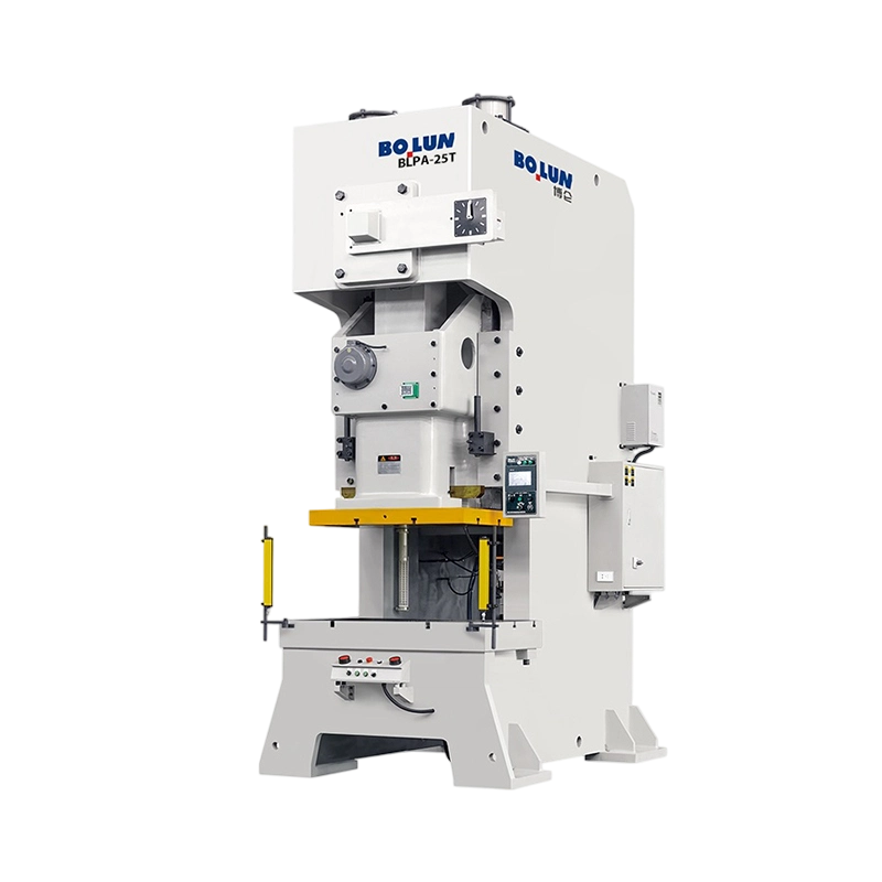
An Open Type Power Press Machine, sometimes called a C frame or gap frame press, uses a frame shaped like the letter C, open on three sides around the working area between the ram and bed.
The open C shaped frame leaves the front and both sides of the working area accessible, which is the defining practical advantage of this design. Material can be fed from the front or either side, dies can be changed with comparatively easy access, and operators or automated feed systems have a clear line of sight and physical access to the working area throughout operation.
The open frame design, while highly accessible, is inherently less rigid than a fully closed frame, since the C shape allows a small amount of frame deflection under load, particularly at higher tonnages or when the load is applied off center within the working area. For this reason, an Open Type Power Press Machine is generally best suited to light and medium tonnage work, commonly up to roughly 250 tons, where the accessibility benefit outweighs the modest precision tradeoff.
Beyond raw accessibility during normal operation, the open C shaped frame of an Open Type Power Press Machine typically allows faster die changeover than a closed frame equivalent, since technicians can approach the die space from three directions rather than being limited to a single front opening. For shops running many different parts through the same press on a rotating schedule, this changeover time advantage can meaningfully increase overall equipment utilization across a working shift, often making the difference between meeting a tight delivery schedule and falling behind.
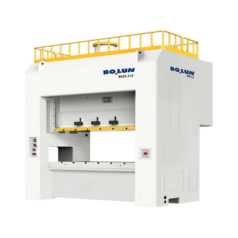
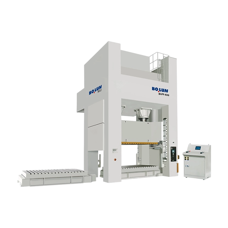
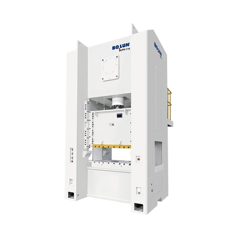
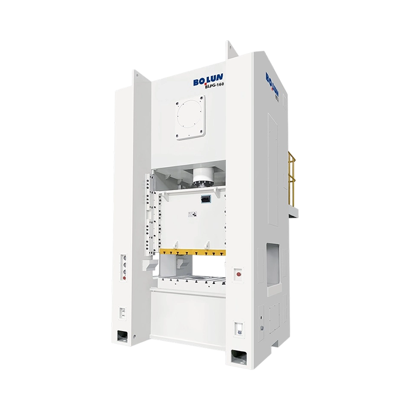
A Closed Type Power Press Machine, often called a straight side press or H frame press, uses a frame with connected structural members on both sides of the working area, forming a fully enclosed load path around the ram.
Because the frame forms a complete load path on both sides rather than an open C shape, a Closed Type Power Press Machine resists deflection far more effectively under heavy or off center loading. This added rigidity translates directly into better ram parallelism and more consistent tooling contact across the full working area, which matters significantly for precision stamping and large panel forming work.
Closed frame construction supports substantially higher tonnage ratings than open frame designs, with many closed type presses rated well beyond 500 tons and large automotive body panel presses reaching several thousand tons. The improved rigidity of a closed frame design generally translates into tighter dimensional tolerances on finished parts, which is why high precision stamping and large panel work consistently favor closed type construction over open type alternatives.
Closed type presses typically employ more extensive slide guiding systems than open type equivalents, often using guide surfaces on all four corners of the ram rather than a simpler two point guide arrangement. This more comprehensive guiding contributes further to the precision advantage of closed frame construction, since it constrains ram motion to a consistent vertical path even when die forces are not perfectly centered within the working area, a scenario that occurs routinely in real production even with well designed tooling.
The table below places the key differences between the two frame types side by side for direct comparison.
| Factor | Open Type Power Press Machine | Closed Type Power Press Machine |
|---|---|---|
| Frame shape | C shaped, open on three sides | Fully enclosed load path on both sides |
| Accessibility | Excellent, open front and sides | Limited to front opening only |
| Frame rigidity | Moderate, some deflection under load | High, minimal deflection under load |
| Typical tonnage range | Up to roughly 250 tons | 250 tons up to several thousand tons |
| Precision and repeatability | Good for general stamping work | Superior for tight tolerance work |
| Relative equipment cost | Lower | Higher |
Neither frame type is universally better, since the correct choice depends entirely on part size, required tolerance, tonnage, and how frequently dies need to change during production, a decision framework covered in more detail later in this guide.
Beyond frame construction, mechanical power presses are further categorized by the specific mechanism used to convert flywheel energy into ram motion, and each drive type produces a distinct force and speed profile through the stroke.
The most common mechanical press design, using a crankshaft to convert rotary motion into linear ram motion. Crank presses offer a straightforward, reliable design well suited to general purpose blanking, piercing, and forming work.
Uses an eccentric shaft rather than a true crankshaft, often allowing a more compact frame design for a given stroke length, commonly used in small to medium tonnage presses.
Uses a knuckle joint linkage that multiplies force dramatically near the bottom of the stroke, making this design well suited to coining, sizing, and precision forming operations requiring very high force over a short working distance.
Similar in principle to a knuckle joint press, using a toggle linkage to generate high force with a controlled, dwell like motion near bottom dead center, favored for operations needing extended contact time under load.
Uses a rotating screw mechanism driven by a flywheel or motor to drive the ram, offering energy limited rather than stroke limited operation, commonly used in forging and coining applications where controlled impact energy matters more than fixed stroke geometry.
Uses a multi link mechanism to modify the ram's velocity profile through the stroke, often producing a slower approach speed and extended dwell at the bottom of the stroke, useful for deep drawing operations sensitive to ram speed.
Selecting the right drive mechanism starts with identifying what the process actually demands from the ram's motion profile. Operations needing fast, simple cutting benefit from standard crank or eccentric drives, since these designs deliver a straightforward, predictable motion at high cycle rates. Operations needing extreme force concentrated near bottom dead center, such as coining fine detail into a part surface, benefit from knuckle joint or toggle designs specifically because of how those mechanisms multiply force through their linkage geometry. Matching drive mechanism to process demand, rather than defaulting to a standard crank press for every application, often improves both part quality and tooling life, and can meaningfully reduce scrap rates on processes where force timing through the stroke directly affects the finished part.
Larger power press machines are also classified by how many connection points, meaning individual crankshaft or eccentric connections, support and drive the ram, which directly affects load distribution across wide working areas.
A single point press uses one central drive connection to the ram, which is the simplest and most common configuration for small to medium sized presses handling parts that fit comfortably within a compact working area without requiring support across an unusually wide span.
A double point press uses two drive connections positioned across the width of the ram, distributing load more evenly across wider working areas and reducing the risk of ram tilt when force is applied off center within a larger die space.
A four point press uses four drive connections, one near each corner of the ram, providing the most even load distribution available and making this configuration the standard choice for very large panel stamping applications, such as automotive body panels, where maintaining consistent parallelism across a large working area is essential to part quality.
As working area increases, the risk of uneven force distribution and ram tilt increases proportionally, which is precisely why larger closed type presses commonly use double or four point configurations rather than a single central drive. Matching point count to part size and tonnage is one of the most important specification decisions when selecting a large format stamping press.
While additional drive points improve load distribution, they also add mechanical complexity, since each additional connection point requires its own precisely synchronized drive linkage tied back to a common flywheel and clutch system. This added complexity generally increases both the initial equipment cost and the ongoing maintenance requirements compared to a simpler single point design, which is why point count should be matched to actual part size requirements rather than selected as a default upgrade regardless of application, since paying for synchronization complexity the actual production need does not require rarely improves overall return on the equipment investment.
Stores rotational energy from the drive motor continuously, releasing it in a concentrated burst during each working stroke to deliver force well beyond what the motor alone could sustain.
Engages the flywheel to the crankshaft to initiate a stroke and stops ram motion promptly once the stroke completes, a critical safety and control component on every power press machine.
Converts the flywheel's rotary motion into the linear reciprocating motion of the ram, with shaft geometry directly determining stroke length and ram speed profile.
The moving component that carries the upper die and delivers force to the workpiece, guided precisely within the frame to maintain consistent alignment with the fixed bed throughout each stroke.
The fixed lower structure supporting the lower die, engineered to withstand repeated impact loading while maintaining precise alignment with the ram across the machine's service life.
Modern power press machines include programmable controls governing stroke speed, safety interlocks, and operational monitoring, increasingly integrated with automated feed and part handling systems on high volume lines.
Every one of these components depends on the others functioning correctly for the press to operate safely and produce consistent parts. A perfectly maintained flywheel and crankshaft cannot compensate for a worn clutch and brake assembly that fails to stop the ram reliably, and a precisely aligned ram guide system offers little benefit if the bed and bolster plate have shifted out of alignment over years of heavy use. Evaluating a press purchase, or planning a maintenance program for an existing machine, means considering the complete system rather than any single component in isolation.
Facilities selecting a power press machine should weigh not only current part requirements but reasonably anticipated future production needs, since upgrading tonnage or frame type later typically means purchasing an entirely new machine rather than modifying an existing one. Specifying moderate additional capacity beyond immediate requirements, where budget allows, often proves more cost effective over the equipment's service life than repeatedly outgrowing successive undersized presses, particularly for growing operations that expect part complexity or volume to increase within a few years of the initial purchase.
The press itself is only one half of a functional stamping operation, since the die determines the actual shape, cutting action, or forming result applied to the material, and die design must align closely with the specific press type selected.
Progressive dies perform multiple operations in sequence as strip material advances through several stations within a single die set, and this approach pairs particularly well with high speed open type presses running continuous coil feed, since the combination maximizes output for parts requiring several forming or cutting steps.
Transfer dies move individual blanks or parts between stations using a mechanical transfer system rather than a continuous strip, an approach commonly used on larger closed type presses producing bigger parts such as automotive panels, where individual blanks rather than a continuous coil feed the process.
Compound dies perform multiple cutting operations simultaneously in a single station rather than across sequential stations, often used for parts requiring high dimensional accuracy between multiple cut features on a single stroke.
Die weight, shut height, and required working clearance must all be checked against the specific press frame type under consideration, since a die designed for the open access and shorter shut height typical of an open type press may not transfer directly to a closed type press without modification, and vice versa.
A poorly maintained die, with dull cutting edges or worn forming surfaces, forces the press to work harder than necessary to complete each operation, accelerating wear on the clutch, brake, and drive components over time. Facilities that treat die maintenance and press maintenance as a single integrated program, rather than two separate concerns handled by different departments, generally see longer service life from both the tooling and the press itself, along with more consistent part quality across the full life of a production run.
The area where the ram and die contact the workpiece, known as the point of operation, represents the highest risk zone on any power press machine, and appropriate guarding, whether fixed barriers, light curtains, or two hand control systems, is essential to prevent operator contact with moving components during a stroke, regardless of the specific frame type or tonnage rating involved.
Since the clutch and brake assembly controls exactly when the ram moves and stops, regular inspection and maintenance of this system is a critical safety requirement, and any sign of delayed stopping or inconsistent engagement should immediately take the machine out of service until repaired.
Consistent operator training on proper feeding technique, die changing procedures, and emergency stop protocols reduces incident risk significantly, and facilities should maintain documented standard operating procedures specific to each press and die combination in regular use.
Any maintenance, die change, or adjustment work performed on a power press machine should follow strict lockout and tagout procedures, ensuring the machine cannot unexpectedly cycle while personnel are working within or near the point of operation.
Continuous power press operation generates significant noise and vibration, particularly on larger closed type presses running high tonnage operations. Facilities should evaluate noise exposure against relevant workplace guidelines and consider vibration isolation mounting for presses installed on upper floors or near sensitive equipment, since transmitted vibration can affect nearby precision machinery over time.
Every power press machine should have clearly marked, easily reachable emergency stop controls positioned so that any operator or nearby personnel can halt the machine immediately without needing to reach across or near the point of operation to do so, and these controls should be tested regularly as part of routine safety verification rather than assumed functional indefinitely after initial installation, since an emergency control that fails silently offers no real protection when it is actually needed.
Different industries gravitate toward specific power press configurations based on the part sizes, tolerances, and production volumes typical of their products.
Automotive body panel production relies heavily on large closed type presses, often in four point configurations, capable of stamping large, complex panels with tight dimensional consistency across thousands of parts per production run. Smaller automotive components, such as brackets and fasteners, are frequently produced on higher speed open type presses running progressive dies.
Appliance housings and internal components span a wide tonnage range, with smaller open type presses commonly handling internal brackets and mounting components while larger closed type presses form exterior panels requiring a smooth, consistent surface finish.
Electrical enclosure manufacturing typically favors open type presses running high speed progressive dies, since these parts are generally lighter gauge material produced in very high volumes where cycle speed and die accessibility for frequent tooling changes matter more than the extreme rigidity closed type presses offer.
High volume fastener and small hardware production commonly uses compact single point open type presses running at very high strokes per minute, prioritizing raw cycle speed over the precision advantages that matter more for larger, tighter tolerance parts.
Heavy industrial applications, including structural bracket forming, thick plate blanking, and large flange forming, typically require the highest tonnage closed type presses available, since material thickness in these applications demands substantially more force per unit of shear or forming length than typical thin gauge sheet metal work found in automotive or appliance manufacturing, often pushing tonnage requirements well beyond what a comparable thin gauge operation would ever need.
Beyond frame type and drive mechanism, several specific numeric specifications determine whether a given power press machine actually fits a production requirement.
Tonnage represents the maximum force a press can safely deliver, and this figure should always exceed calculated required force for a given operation by a reasonable safety margin, since running a press consistently near its maximum rated tonnage accelerates wear and increases failure risk.
Stroke length defines the total vertical travel distance of the ram, which must be sufficient to allow parts to clear the die during removal or automatic ejection, particularly important for deep drawn parts requiring greater clearance than simple blanking operations.
This figure directly determines maximum theoretical production rate, though actual achievable output also depends on material feed speed, part complexity, and any secondary operations integrated into the press cycle.
Shut height, the distance between the ram and bed at the bottom of the stroke, must accommodate the specific die height being used, while bed size must physically fit both the die and the material being fed through the press.
Beyond the specifications a buyer directly interacts with, motor power and flywheel energy capacity determine how quickly a press can recover between strokes at sustained high production rates. A press running near its maximum rated strokes per minute for extended periods needs adequate motor power to keep the flywheel fully charged between cycles, and undersized motor capacity can cause gradual speed loss and inconsistent force delivery during long continuous production runs, an issue that specification sheets alone do not always make obvious without checking duty cycle ratings specifically, which is why requesting duty cycle data directly from a manufacturer is worthwhile before finalizing a purchase decision.
Power press machines are primarily classified by frame construction into Open Type and Closed Type designs, and by drive mechanism into mechanical, hydraulic, and pneumatic presses, with mechanical presses further divided by crank, eccentric, knuckle joint, toggle, and screw drive types.
An Open Type Power Press Machine uses a C shaped frame open on three sides for easy access, generally suited to lighter tonnage work, while a Closed Type Power Press Machine uses a fully enclosed frame offering greater rigidity and precision for higher tonnage and larger part applications.
Open Type Power Press Machines commonly cover tonnage up to roughly 250 tons, making them well suited to small and medium stamping, blanking, and piercing operations rather than very large panel work.
Closed Type Power Press Machines offer significantly greater frame rigidity, which reduces deflection under heavy or off center loading and maintains tighter ram parallelism, both of which are essential for producing large, dimensionally consistent panels.
A mechanical press machine uses a flywheel and crankshaft to convert stored rotational energy into fast, repeatable ram strokes, while a hydraulic press uses fluid pressure to deliver constant force throughout the stroke at generally slower cycle speeds.
A knuckle joint press uses a linkage mechanism that multiplies force dramatically near the bottom of the stroke, making it well suited to coining, sizing, and other precision operations requiring very high force over a short working distance.
Point count refers to the number of individual crankshaft or eccentric drive connections supporting the ram, ranging from single point presses for compact parts to double or four point presses that distribute load evenly across wider working areas.
Required tonnage depends on material thickness, material strength, the shear or forming perimeter length of the part, and the specific operation being performed, and is typically calculated using established formulas specific to blanking, piercing, or forming work.
Essential safety features include point of operation guarding such as light curtains or fixed barriers, a reliable clutch and brake system with verified stopping performance, two hand control systems where applicable, and documented lockout and tagout procedures for maintenance work.
Clutch and brake systems should be inspected on a regular schedule defined by the manufacturer and applicable safety regulations, with stopping distance and response time verified to remain within specified safety tolerances at every inspection interval.


Understanding Mechanical Power Presses and Their Essential Functions A mechani...
What Is a Power Press? A power press — also called a stamping press or punch pr...
As the manufacturing industry moves steadily toward automation and smart product...
In the fields of metal forming, sheet metal fabrication, blanking, and punching,...
In modern manufacturing, cold forging is widely used in the automotive, aerospac...
Manufacturing & Metalworking A direct, practical look at how mechanical pre...
Contact Us

+86-575-83362228

+86-13735238388

+86-575-83362999

+86-15158259588

Hangzhou Office Add: No. 332 Wangjiang East Road, Shangcheng District

No.1 Linjiang Road East, Xiaren, Jinting Town, Shengzhou City, Zhejiang Province, China
Ready to Begin?
Get in Touch

Now!

ZHEJIANG BOLUN
 English
 中文简体
中文简体
